A Calibration Factor Block Layout
A-766 N1911A/1912A P-Series Power Meters Programming Guide
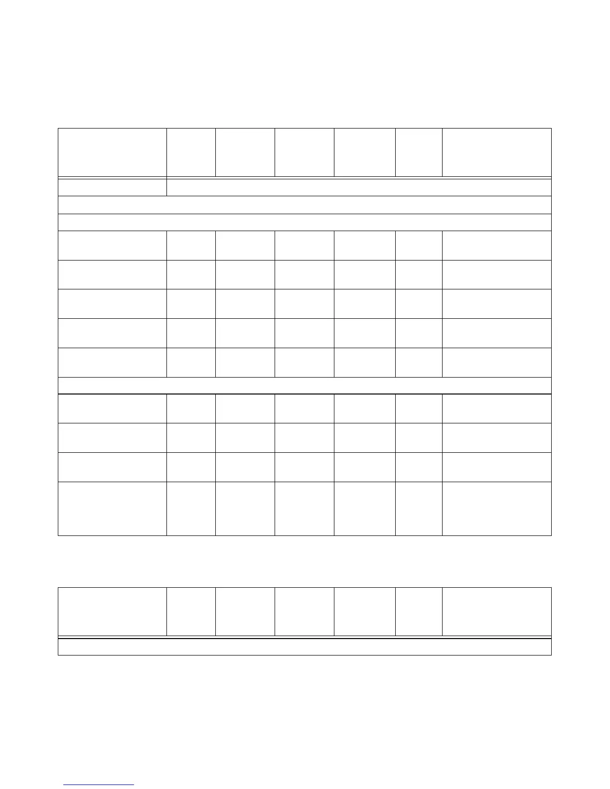
Tab le A-9 8 Calibration Factor Block Layout: E9320 Series Sensors
Header Total: 6
For Each Table (tables are in the order of lower to upper):
Power, low 2 - 7.8 (signed) –127.9 to
+127.9
dBm Power for low power
flatness.
Power, high 2 - 7.8 (signed) –127.9 to
+127.9
dBm Power for high power
flatness.
Frequency (point ‘0’) 4 - 32 bit fixed 0 to Fhpb*
(2^32)
None Fhpb = freq Hz per bit
Cal factor (low power)
1
2 - 2.14 0.25 to 3 None Power (in watts) is
divided by this value.
Cal factor (high power)
1
2 - 2.14 0.25 to 3 None Power (in watts) is
divided by this value.
These table entries are repeated as shown for each frequency point
Frequency (point ‘N’) 4 - 32 bit fixed 0 to Fhpb*
(2^32)
None Fhbp = Freq Hz per bit.
Cal factor (low power) 2 - 2.14 0.25 to 3 None Power (in watts) is
divided by this value.
Cal factor (high power) 2 - 2.14 0.25 to 3 None Power (in watts) is
divided by this value.
Tab le siz e:
-
See note
1
The table size is
dependent on the
number of frequency
points.
E9300 Series
Sensors: Calibration
Factor Block Layout
No.
Bytes
Contents Data
Format
Data
Range
Units Notes
E9320 Series
Sensors: Calibration
Factor Block Layout
No.
Bytes
Contents Data
Format
Data
Range
Units Notes
Header:

 Loading...


