A Calibration Factor Block Layout
A-768 N1911A/1912A P-Series Power Meters Programming Guide
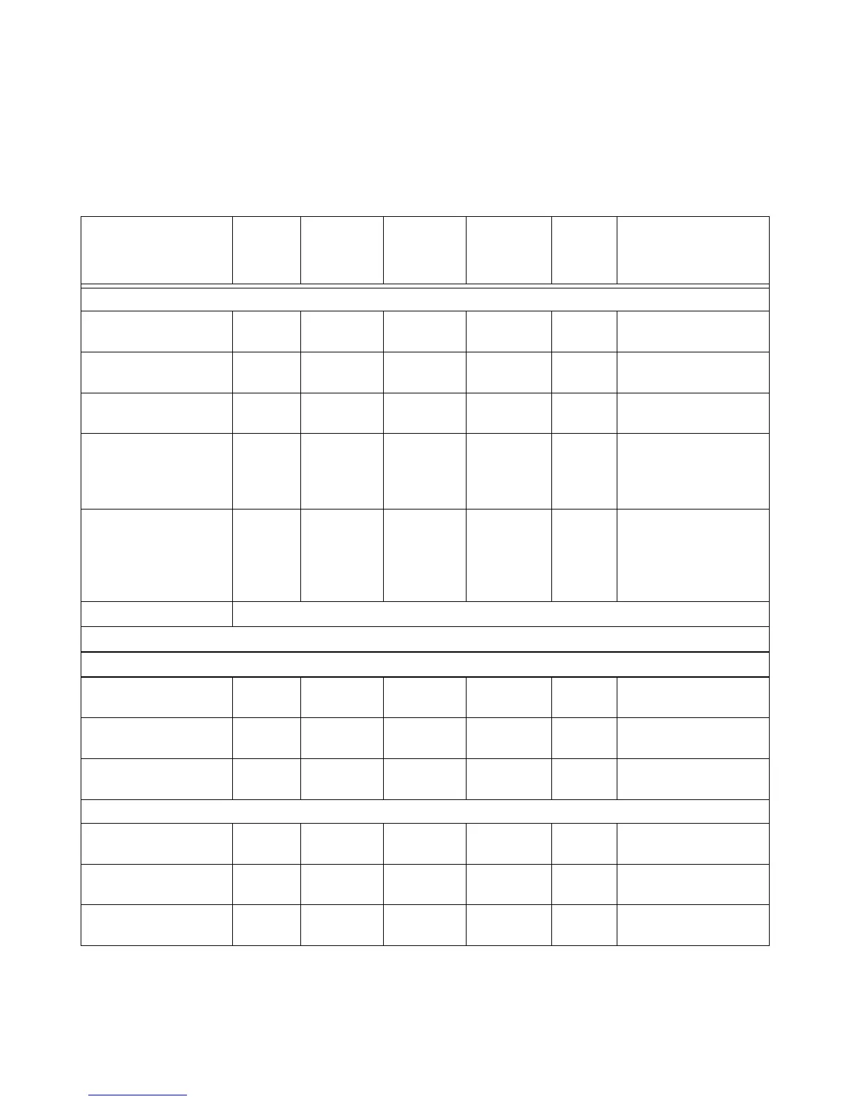
Tab le A-9 9 Calibration Factor Block Layout: N8480 Series Sensors
N8480 Series
Sensors: Calibration
Factor Block Layout
No.
Bytes
Contents Data
Format
Data
Range
Units Notes
Header:
Power, low 2 - 7.8 (signed) –127.9 to
+127.9
dBm Power for low power
flatness.
Power, high 2 - 7.8 (signed) –127.9 to
+127.9
dBm Power for high power
flatness.
Number of frequency
points
2 - 16 bit
integer
-None
Bytes per frequency
point
1 - - - None Number of bytes in cal
factor value at each
frequency and power
level.
Frequency LSB weight 2 1000 - Hertz Fhbp (Freq. Hz per bit).
1 KHz per bit for the cal
factor: 1 KHz x 2^32 =
4.3E+12 = 4300 GHz
range
Header Total: 9
Cal Factor Table:
Frequency (point ‘0’) 4 - 32 bit fixed 0 to Fhpb*
(2^32)
None Fhpb = Freq Hz per bit
Cal factor (low power)
1
2 - 2.14 0.25 to 3 None Power (in watts) is
divided by this value.
Cal factor (high power)
1
2 - 2.14 0.25 to 3 None Power (in watts) is
divided by this value.
These table entries are repeated as shown for each frequency point
Frequency (point ‘N’) 4 - 32 bit fixed 0 to Fhpb*
(2^32)
None Fhbp = Freq Hz per bit
Cal factor (low power)
1
2 - 2.14 0.25 to 3 None Power (in watts) is
divided by this value.
Cal factor (high power)
1
2 - 2.14 0.25 to 3 None Power (in watts) is
divided by this value.

 Loading...


