EasyManuals Logo

Autonics GP Series User Manual

Autonics GP Series
311 pages
To Next Page IconTo Next Page
To Previous Page IconTo Previous Page
Page #22 background imageLoading...
Page #22 background image
22
1.6 SERIAL CONNECTION SPECIFICATIONS
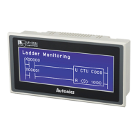
1.6.1 Serial port
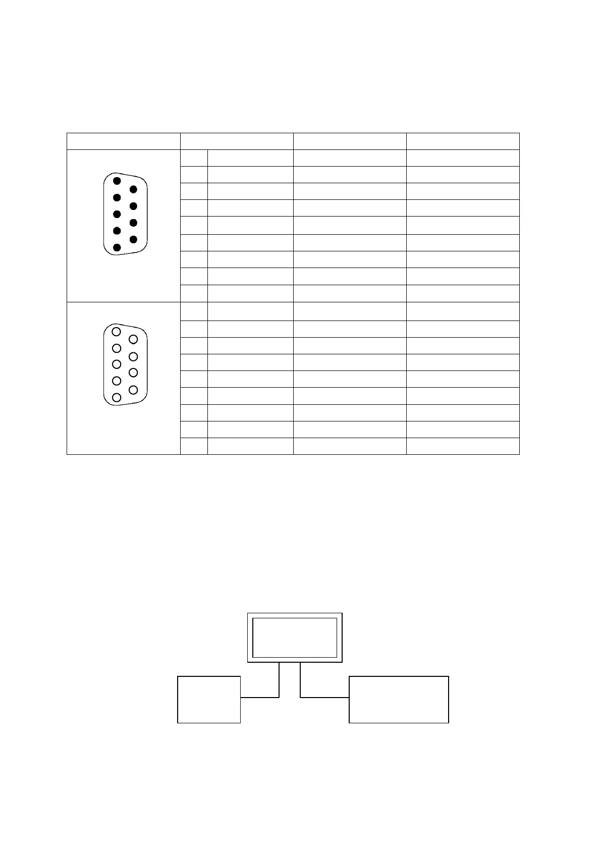
1.6.2 Connection of PLC
•Refer to “Communication manual” for connection because the wiring of each PLC model is different.
•All devices including PLC can be connected to RS232C/RS422.
CH1, CH2 are designated in editor.
Connection of 1 PLC
Connect PLC to a port and one of PC, Printer, Barcode reader to another port.
Port
Pin(GP-2480)
Pin(GP-S057)
Pin(LP-S044)
RS232C
1
Non-used
Non-used
Non-used
2
RXD
RXD
RXD
3
TXD
TXD
TXD
4
DTR
DTR
DTR
5 SG SG SG
6
DSR
DSR
DSR
7
Non-used
Non-used
Non-used
8
Non-used
Non-used
Non-used
9
Non-used
Non-used
Non-used
RS422 1 TXD+ TXD+ TXD+
2
RXD+
RXD+
RXD+
3
RTS-
Non-used
Non-used
4
CTS+
Non-used
Non-used
5
SG
SG
SG
6 TXD- TXD- TXD-
7
RXD-
RXD-
RXD-
8
RTS+
Non-used
Non-used
9
CTS-
Non-used
Non-used
PC, Printer
Barcode reader
PLC
GP
5
4
3
2
1
9
8
7
6
D-Sub 9Pin
Male
1
2
3
4
5
6
7
8
9
D-Sub 9Pin
Female

Table of Contents

Questions and Answers:

Question and Answer IconNeed help?

Do you have a question about the Autonics GP Series and is the answer not in the manual?

Autonics GP Series Specifications

General IconGeneral
BrandAutonics
ModelGP Series
CategoryControl Panel
LanguageEnglish