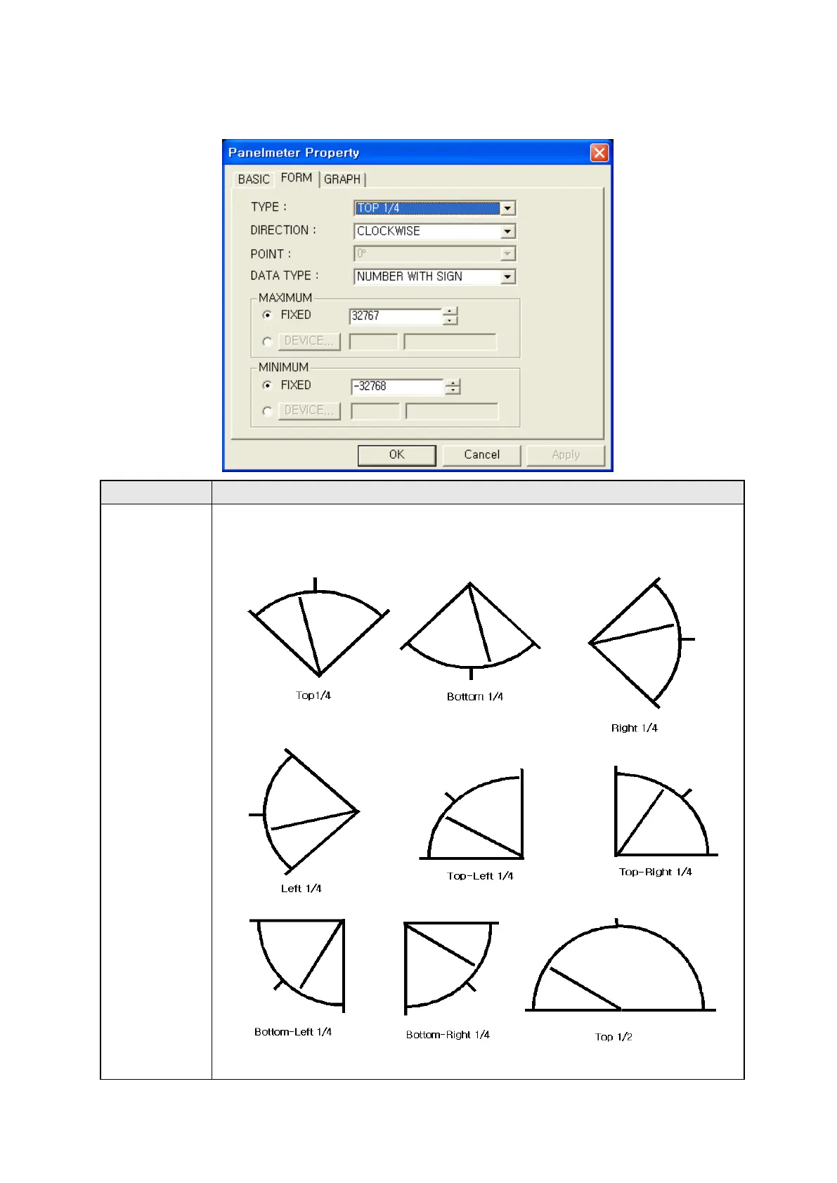
Home
Autonics
Control Panel
GP Series
Autonics GP Series User Manual
4
of 1
of 1 rating
311 pages
Give review
Manual
Specs
To Next Page
To Next Page
To Previous Page
To Previous Page
Loading...
260
29.3.2 Form tap
Form t
ap
Designate
panel m
eter t
ype and r
ange of v
alue
â‘
Typ
e
•
Designat
e panel m
eter t
ype.
Up 1/4,
Down 1/
4, Left 1
/4, Righ
t 1/4, T
op
-
left1/4, T
op
-
right1/4, Do
wn
-
left 1/4,
Do
wn
-
rig
ht 1/4, U
p 1/2, R
ight 1/
2, Left 1/2, D
own 1/2,
3/4, C
ircle
â‘
â‘¡
â‘¢
â‘£
⑤
â‘¥
⑦
â‘§
⑨
â‘©
⑪
â‘«
259
261
Table of Contents
Default Chapter
6
Table of Contents
6
1 Outline
15
Outline
15
The Definition of Gp
15
The Feature of Gp2480
16
Ordering Information
17
The Rating
18
Specifications
20
Connection of PLC
22
Serial Connection Specifications
22
Serial Port
22
Configuration of Serial Port
23
Dimensions and Description of Parts
24
Parts Description
24
Dimensions
27
The Fixing Bracket (20060407)
28
Panel Cut-Out
30
Installation Procedure
31
Battery Replace
32
Precaution for Using
32
The Wiring of Power
32
2 Start up
33
Start up Procedure
33
Initial Screen Display
34
3 System Display
35
Organization of System Display Screen
35
Operation of System Display Screen
36
Monitoring Menu
37
Device Monitoring
37
Monitoring I/O Device
38
Data Check Mode
39
Base Display Screen
39
Window Screen
39
Comment List
40
Check Used Memory
40
Preference Menu
41
Selection of Language
42
Connection of PLC
43
Current Time
47
Delete User Data
48
Configuration/Access Key
50
Buzzer
51
Switching of User Screens
51
Backlight
52
Battery
53
Screen Contrast
54
Function Configuration Mode
55
Data Transmission
55
Time Switch
56
Print out
57
4 User Screen
58
Screen Specification
58
Screen Display Objects
61
Screen Switching
62
Display of Device Connection Status
65
5 System Key Window
66
Keypad Types
66
Organization of Keypad
67
6 The Outline of Gp Editor
68
Organization of Editor Program Window
68
Organization and Description of Main Menu
69
Description of Tools
73
7 Project Operation
76
Create Project
76
Startup Program
76
Create New Project
77
Configuration of Gp/Plc Type
78
Configuration of Project Auxiliary Property
79
Configuration of Format Type
79
Configuration of Key Window Display
79
Configuration of Key Window
80
Configuration of Serial Port
81
Configuration of Project Option
82
Configuration of Overwrite Message
82
Configuration of Backup File
82
Communication Configuration of PC/GP
84
Configuration of Language and Font
85
Configuration/Access Key for System Menu
86
Other Auxiliary Configurations
87
Save/Open Project
88
Save Project
88
Import Project
90
Import Base Screen
90
Import Window Screen
92
Operation Procedure of Import Parts
92
Print out Project
95
Print Procedure
95
Creating Folder When Printing as File
97
End Project
97
8 Screen Operation
98
Gp Screen
98
Base Screen
98
Window Screen
98
Create New Screen
100
Operation Procedure
100
Adjustment after Design
101
Precaution of Designing Key Window
101
Screen Property
103
Load Screen
104
Operation Procedure
104
Detail Description of Load Screen Window
104
Clear Screen
105
Store Screen
105
Store as
106
Copy/Delete Screen
107
9 Edit
108
Undo Operation
108
Cut Objects
108
Delete Objects
108
Copy Objects
108
Paste Objects
108
Successive Copy
109
Selection Objects
111
Select All Objects
111
Stacking Order
111
Stacking Order between Objects
111
Change Stacking Order between Objects
112
Group
113
Ungroup
114
Alignment
114
Horizontal Alignment
114
Vertical Alignment
115
Equal Interval of Alignment
116
Calling of Property Window
117
Device Replacement
117
10 Draw
118
Draw Figures
118
Draw Lines
118
Draw Rectangles
119
Draw Circles
120
Text
121
Bitmap
123
Draw Tags
124
Object Selection, Movement and Size Adjustment
125
Select an Object
125
Move an Object
126
Adjust Size of Object
126
Part/Panel Kit Library
127
Panel Kit Window
127
View/Draw Contents of Library
128
Create/Delete Panel Kit Library
128
Register/Delete/Copy Kit in Panel Kit Library
129
Save/Import Panel Kit Library
129
Register/Copy/Delete/Draw Part
130
Overlap Screen
131
Designation of Key Window Position
133
11 Communication
134
Outline
134
Download Design Data
134
Precaution of Configuration
134
Detail Description of Download Window
135
Upload
138
Upload Procedure
138
Detail Description of Upload Window
139
Memory Function
141
Operation Procedure
141
Detail Description of Memory Window
141
Data Check
142
Check Tap of Area
143
Check Tap of Store Memory Option
144
Level Password Tap
144
Common Device
145
Firmware Download
146
12 View
149
Tag List
149
All Taps
149
View Device List
152
View Overlap Screen List
154
Preview
155
Tool Palette
155
View On/Off Image
155
Screen Refresh
155
Status Bar
155
Tool Bar
156
13 Common Configuration
157
Configuration of Project Information
157
Screen Information
157
Configuration of Screen Information
158
Comment
159
Change Plc Type
161
PLC Connection
161
Configuration of Connection PLC with GP/PLC Type Window
162
Data Link of CH1
163
Data Link of CH2
165
Switch Device for Changing PLC Type
168
14 Figure
170
Detail Configuration
170
Edit Procedure in Editor
170
Line
170
Detail Configuration
171
Edit Procedure in Editor
171
Rectangle
171
Circle
172
Detail Configuration
172
Edit Procedure in Editor
172
Detail Configuration
173
Edit Procedure in Editor
173
Text
173
Bitmap Image
175
15 Numeral Display
176
Procedure of Basic Configuration
176
Basic Operation
176
Detail Configuration
177
Basic Tap
177
Form Tap
178
Operation Tap
179
Display Type and Operation
180
Numeral Display Range for Data Type (Operation Is Not Applied.)
180
Numeral Display Procedure
180
32Bit Floating-Point Type (IEEE Standard 754)
181
Real Number Display of GP
182
16 Ascii Display
184
Basic Configuration
184
Basic Operation
184
Detail Configration and Operation in Main Device
185
Basic Tap
185
Form Tap
186
17 Numeral Input
187
Basic Configuration
187
Basic Operation
187
Derail Configuration
189
Basic Tap
189
Form Tap
190
Trigger Tap
191
Other Tap
192
Operation in Numeral Input
193
18 Ascii Input
194
Basic Configuration
194
Basic Operation
194
Detail Configuration and Operation in Main Device
196
Basic Tap
196
Form Tap
197
Trigger Tap
198
Option Tap
199
19 Time Display
200
Basic Operation
200
Detail Configuration
201
Basic Tap
201
Form Tap
202
20 Comment Display
203
Basic Operation
203
Bit Operation
203
Word Operation
203
Basic Configuration
204
Detail Configuration
205
Basic Tap
205
Bit
206
Word
207
21 Alarm History
208
Basic Function in Gp
208
Edit
208
Common Configuration of Alarm History
209
Basic Tap
209
Monitor Device Tap
211
Configuration of Alarm History Tag Property
213
Basic Tap
213
Form Tap
214
Format Tap
215
Touch Key for Alarm History
216
22 Alarm List
220
Edit Procedure in Editor
220
Basic Operation
220
Detail Configuration and Operation of Main Device
221
Basic Tap
221
Form Tap
222
Option Tap
223
Detail Display Tap
224
Alarm Detail Information
225
23 Part Display
226
Basic Operation
226
Bit Operation
226
Word Operation
227
Edit Procedure in Editor
227
Detail Configuration and Operation
228
Basic Tap
228
Bit Tap
230
Word
231
24 Lamp Display
232
Edit Procedure in Editor
232
Basic Operation
232
Detail Configuration
233
Basic Tap
233
Bit Tap
234
25 Line Graph
236
Basic Function
236
Edit Procedure of Line Graph in Editor
236
Detail Configuration and Operation of Main Device
237
Basic Tap
237
Form Tap
238
Monitor Device Tap
239
Case Tap
240
Other Tap
241
26 Trend Graph
242
Basic Function
242
Edit Procedure of Trend Graph in Editor
242
Detail Configuration and Operation of Main Device
243
Basic Tap
243
Form Tap
243
Monitor Device Tap
245
Case Tap
246
Other Tap
247
27 Bar Graph
248
Basic Function
248
Bar Graph Edit Procedure in Editor
248
Detail Configuration
249
Basic Tap
249
Form Tap
250
Monitor Device Tap
251
Case Tap
252
Other Tap
253
28 Statistics Graph
254
Basic Function
254
Statistikcs Graph Edit Procedure in Editor
254
Detail Configuration
255
Basic Tap
255
Division Tap
256
Graph Tap
257
29 Panel Meter
258
Basic Function of Panel Meter
258
Basic Configuration in Editor
258
Detail Configuration and Operation of Main Device
259
Basic Tap
259
Form Tap
260
Graph Tap
262
30 Touch Key
263
Basic Function of Touch Key
263
Bit Device Configuration
263
Configuration of Word Device
264
Screen Switching
265
Special Function with Key Code
265
Edit Touch Key in Editor
266
Detail Configuration and Operation of Main Device
267
Basic Tap
267
Form Tap
268
Action Tap
270
Option/Trigger Tap
274
31 System Information
275
Outline
275
Read Device
275
System Signal 1
275
Current Recipe Number
276
System Signal 3
276
Reserved Area (12 Points)
276
Write Device
276
Current Base Screen Number (Write Device)
276
Current Overlap Screen Number 1(Write Device+1)
276
Current Overlap Screen Number 2(Write Device +2)
276
Input Tag ID(Write Device+3)
276
System Signal 2(Write Device+4)
277
System Signal 4(Write Device+5)
277
Time and Date (7 Points )
277
Reserved Area (2 Points )
277
Gp Inner Device
278
32 Screen Switching and Overlap Window
279
Overlap Window
279
Configuration and Operation in Editor
279
33 Barcode Reader
281
Specification of Available Barcode Reader
281
Basic Operation
281
Read Procedure of Barcode
282
Save
283
34 Observe Status
285
Basic Operation
285
Operation Procedure
285
Operation Type
286
Detail Configuration and Operation in Editor
287
Project Tap
288
Screen Tap
288
Trigger Tap
289
Operation Tap
290
35 Recipe
292
Configuration in Editor
292
Operation Procedure in Main Device
292
Detail Configuration and Operation in Editor
294
Recipe Window
294
Recipe Property Window
295
Write Trigger Tap
296
36 Security Function
299
Basic Function
299
Detail Configuration and Function in Editor
302
37 Floating Alarm
305
Function
305
Configuration in Editor
306
Floating Alarm Window
306
Screen Auxiliary Configuration
307
38 Time Action
308
4
Based on 1 rating
Ask a question
Give review
Questions and Answers:
Need help?
Do you have a question about the Autonics GP Series and is the answer not in the manual?
Ask a question
Autonics GP Series Specifications
General
Brand
Autonics
Model
GP Series
Category
Control Panel
Language
English