9-23
DS35-W00 May. 2007
CLUTCHCLUTCH
CLUTCHCLUTCH
CLUTCH
TRANSMISSIONTRANSMISSION
TRANSMISSIONTRANSMISSION
TRANSMISSION
ENGINEENGINE
ENGINEENGINE
ENGINE
HSTHST
HSTHST
HST
FRONT AXLEFRONT AXLE
FRONT AXLEFRONT AXLE
FRONT AXLE
STEERINGSTEERING
STEERINGSTEERING
STEERING
BARKEBARKE
BARKEBARKE
BARKE
ELECTRICELECTRIC
ELECTRICELECTRIC
ELECTRIC
INDEXINDEX
INDEXINDEX
INDEX
HYDRAULICHYDRAULIC
HYDRAULICHYDRAULIC
HYDRAULIC
GENERALGENERAL
GENERALGENERAL
GENERAL
REAR AXLEREAR AXLE
REAR AXLEREAR AXLE
REAR AXLE
CK22/CK22H
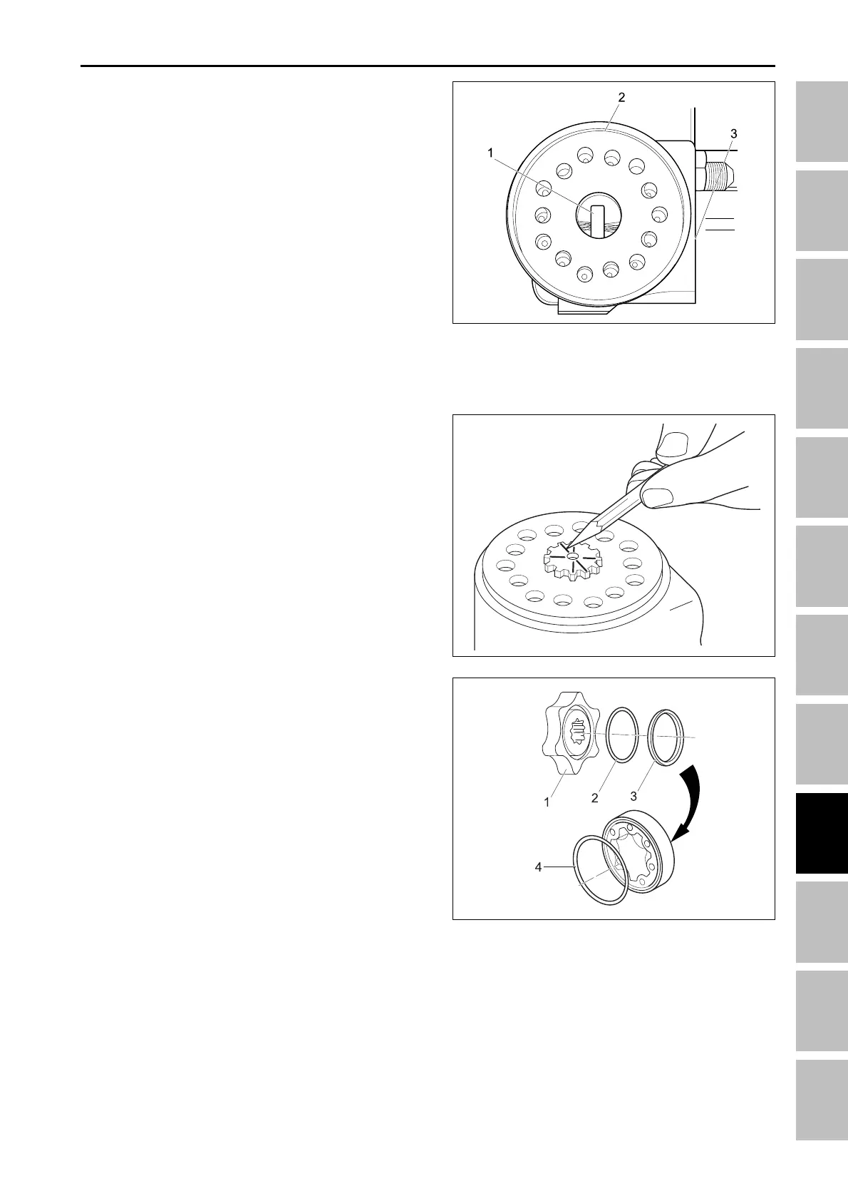
14.Insert the drive shaft (1), into the motor so that its
slotted end engages the pin in the spool and sleeve.
Mark a line (2), on the face of the drive shaft that is
parallel to the pin and to the port face of the steering
motor housing (3).
15.Coat a new O-ring (2), and seal ring (3), with clean
hydraulic fluid and install on the rotor (1). Install a
new O-ring (4), in the groove on the stator, then fit
the rotor and stator together so that their O-ring are
on opposite sides.
NOTE:
• The orientation of the rotor and stator on the drive
shaft will determine valve timing in the steering
motor. These parts must be installed as described.
196W842A
196W843A
(1) Rotor (3) Seal ring
(2) O-ring (4) O-ring
13.Position the spool and sleeve so that the pin (1), is
parallel with the port face of the steering motor hous-
ing (3).
(1) Pin
(2) Spacer plate motor
(3) Port face of steering
196W841A
STEERING SYSTEM - SERVICING