10-15
DS35-W00 May. 2007
CLUTCHCLUTCH
CLUTCHCLUTCH
CLUTCH
TRANSMISSIONTRANSMISSION
TRANSMISSIONTRANSMISSION
TRANSMISSION
ENGINEENGINE
ENGINEENGINE
ENGINE
HSTHST
HSTHST
HST
FRONT AXLEFRONT AXLE
FRONT AXLEFRONT AXLE
FRONT AXLE
STEERINGSTEERING
STEERINGSTEERING
STEERING
BARKEBARKE
BARKEBARKE
BARKE
ELECTRICELECTRIC
ELECTRICELECTRIC
ELECTRIC
INDEXINDEX
INDEXINDEX
INDEX
HYDRAULICHYDRAULIC
HYDRAULICHYDRAULIC
HYDRAULIC
GENERALGENERAL
GENERALGENERAL
GENERAL
REAR AXLEREAR AXLE
REAR AXLEREAR AXLE
REAR AXLE
CK22/CK22H
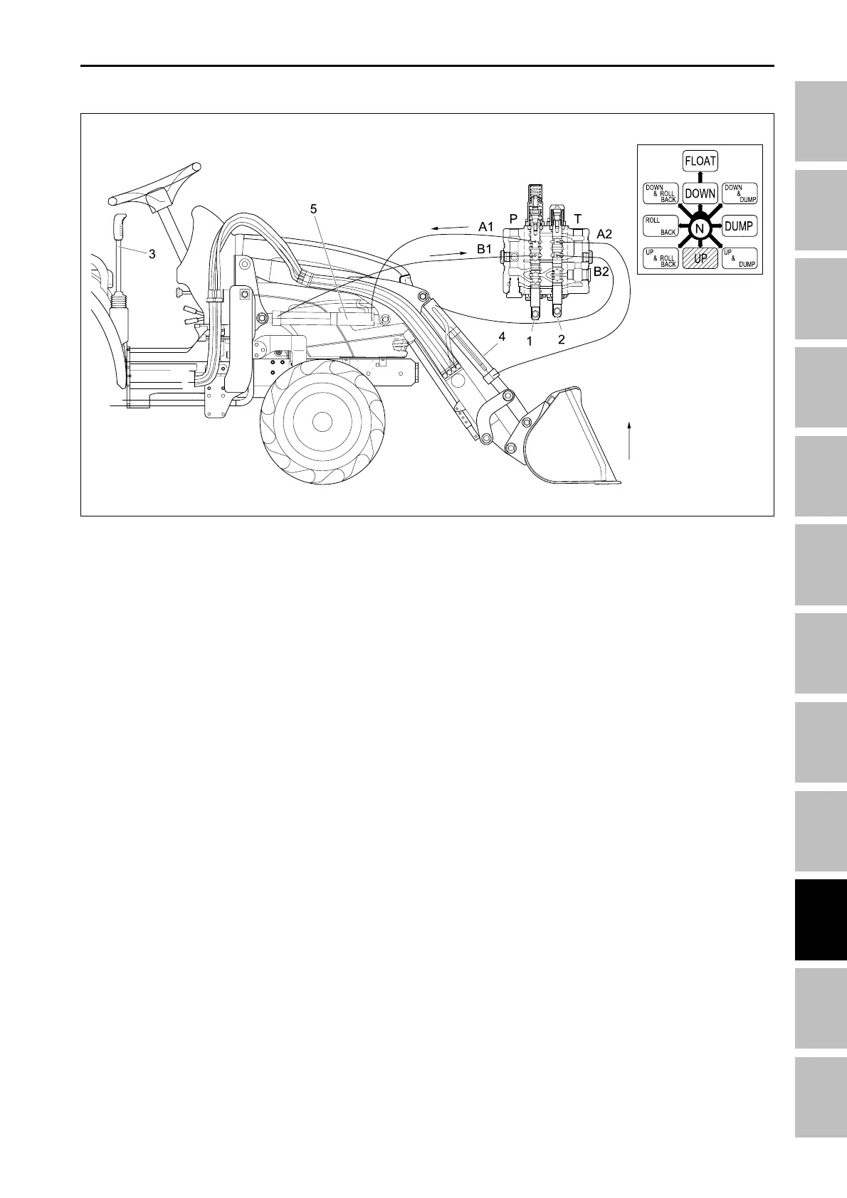
C. RAISING POSITION
(1) Lift control valve spool
(2) Bucket control spool
(3) Control lever
(4) Bucket cylinder
(5) Lift cylinder
When the control lever (3) is moved to the raising posi-
tion the lift control valve spool (2) is moved outward.
Fluid flow from the hydraulic pump and is directed to
the piston side or the lift cylinder (5). The fluid con-
tained in the rod side of the lift cylinder flows out of the
cylinder past port “T” to the transmission case allow-
ing the implement to raise.
Because the bucket control spool (2) is in the neutral
position, the fluid trapped in the bucket cylinder (4) is
blocked by the spool, and the bucket cylinder is held in
a fixed position.
196W922A
HYDRAULIC SYSTME - OPERATING PRINCIPLE