HEADER ATTA CHMEN T/DETACHMENT
15. Place a 6 in. (150 mm) b lock (A) under the header leg.
This will assist with disconnecting the center-link.
16. Disengage comb ine lift cylinder locks, start engine, and
lower header until the header leg rests on the block or
stabilizer whe els are th e ground.
Figure 4.105: Header Leg o n Block
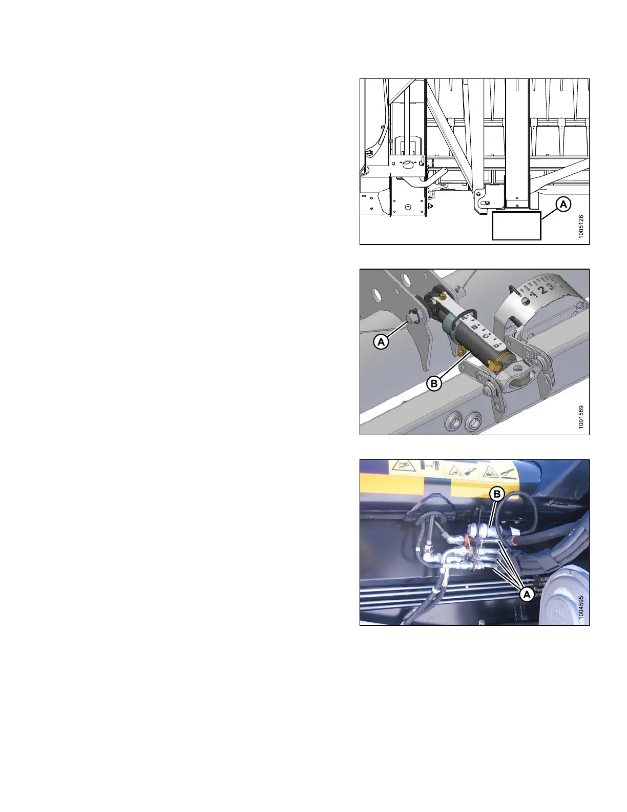
17. Disconnect hydraulic center-link:
a. Remov e lyn ch p in and c levis pin (A), and then lift
center-link (B) clear of bracket.
b. Replace pin (A) and secure with lynch pin.
NOTE:
Feeder ho
use may need to be raised or lowered, or
length of
link adjusted, to relieve load on link.
Figure 4.106: Hydraulic Center-Link
NOTE:
•Ifonth
e ground: Push reel fully forward to reduce
oil los
s.
•Ifontr
ansport: Pull reel fully back.
18. Disconnect electrical connector (B).
19. Disconnect knife and draper drive hydraulic hoses (A)
at bracket. Cap off ends immediately to avoid loss
of oil.
20. Store and secure hoses on adapter frame.
Figure 4.107: Header Connections
147695 243 Revision A