OPERATION
7. Place wing lock spring ha ndles (A) in lo ck
(upper) position.
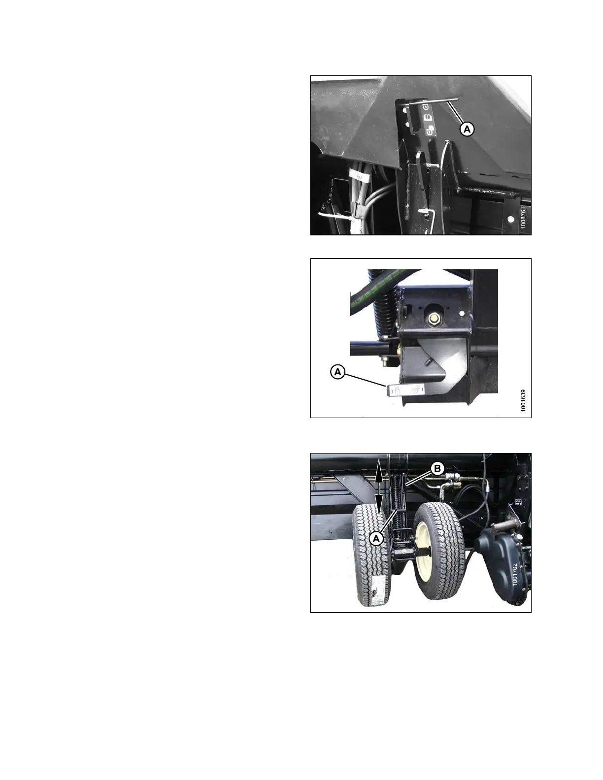
Figure 3.38: Wing Lock in Lock Position
8. Move both header float lock lev ers (A)
down (UNLOCK).
Figure 3.39: Header Float Lock in
UNLOCK Position
9. Place stabilizer wheels and slow speed transport
wheels (if equipped) in storage position as follows:
a. Support the left wheel assembly’s wheel weight by
lifting slightly with one hand. Pull up on handle (A)
to release loc k.
b. Lift wheels to desired height and engage support
channel into slot (B) in upper support.
c. Push down on handle (A) to lock.
Figure 3.40: Left W heels Shown – Right
Wheels Sim ilar
147695 60 Revision A