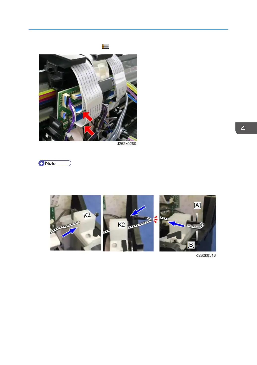
12. Connect the FFCs to the HRB. ( x2)
13. Attach the thermistor to the head tank (K2) of the print head unit.
• Insert the thermistor into the hole of the head tank from left to right, fold back the tip of the
harness, then feed the thermistor back into the hole.
• Insert the sensor head [A] so that it placed above the harness [B] in the hole of the head tank.
14. Place the ink tubes on the path of the print head, from right to left in order of K2 and K1.
• Place the ink tube (K2) [A] on the path of the print head first.
• Then place the ink tube (K1) [B] upon the ink tube (K1) on the path of the print head.
Carriage Unit
443