The illustration above shows carriage unit cradles. The left cradle holds the black print head units (K1,
K2) and the right cradle holds the color print heads units (Y1M1, C, Y2M2).
• The black thermistor (2) monitors the head around the black print head units, and the color
thermistor(3) measures the heat around the color print head units.
• A pair of air sensor terminals (1) is attached to the top of each sub tank.
• The purge valves (4) allow air to escape from the ink sub tank if an air sensor detects too much air
in the tank. The valve is operated by a plunger and air release solenoid (not shown).
• The ink sub tanks (5) hold the ink pumped from the ink cartridges by the ink supply unit.
• One ink sub tank feeler (6) is attached to the side of each ink sub tank. The OCFS (On Carriage Fill
Sensors) and the stationary main ink level sensors on the right side of the machine check the
positions of these feelers to determine the level of ink in the sub tanks. The OCFS actuators are
attached to the right sides of the K1, K2, and C tanks, but the OCFS actuators are attached to both
sides of the Y1M1 and M2Y2 tanks.
• A filter unit (7) is set on top of every print head unit (8) as an extra precaution to keep the ink free
of dirt, paper dust.
• The print heads (9) eject the ink onto the paper.
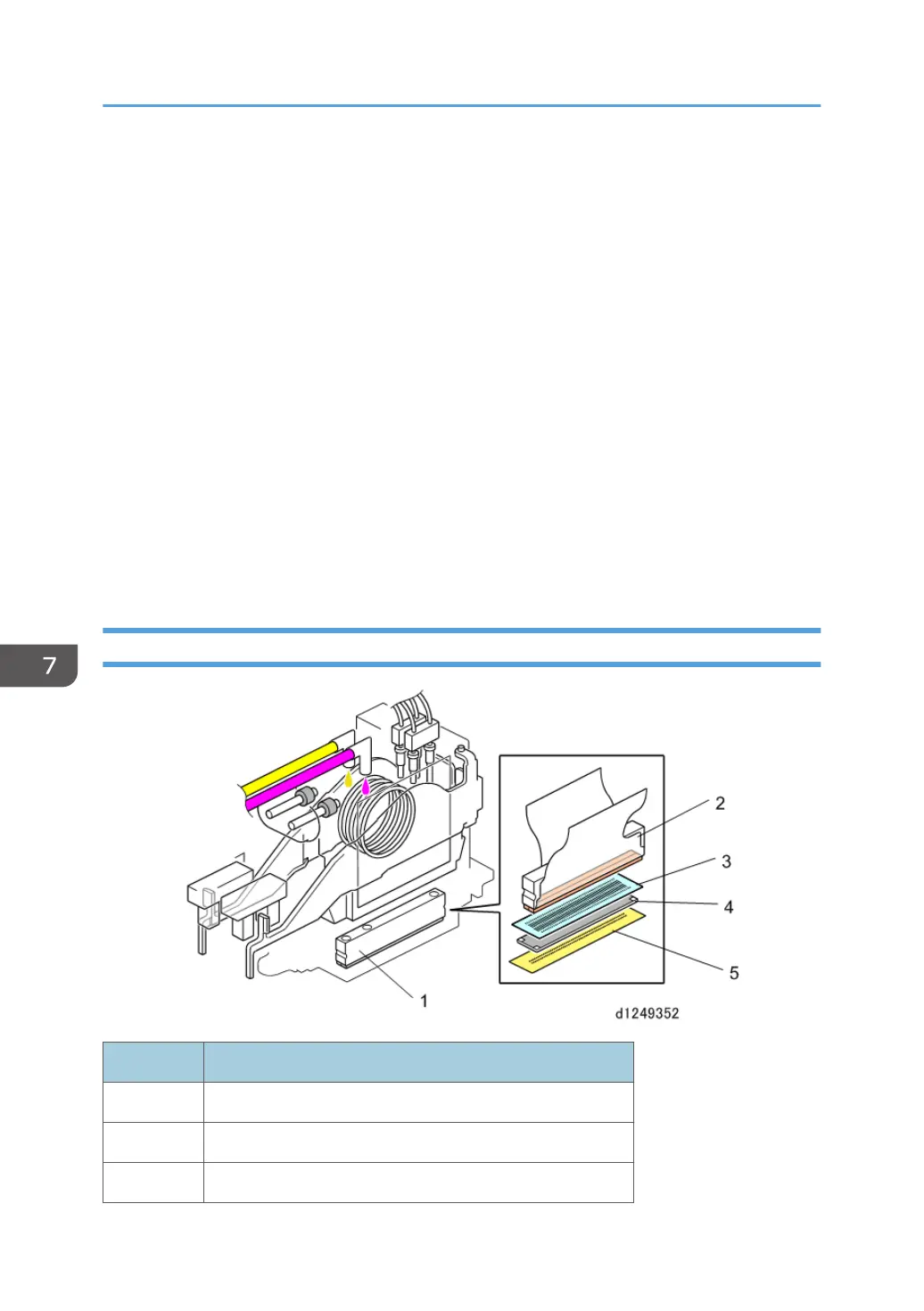
Print Head
No. Item
1 Print head
2 Piezoelectric element
3 Vibration plate
7. Detailed Description
846