PD04
*DI2
Input device
selection 2
Any input device can be assigned to the CN3-12 pin.
Device selection
Refer to table 5.9 in [Pr. PD03] for settings.
PD05
*DI3
Input device
selection 3
Any input device can be assigned to the CN3-19 pin.
Device selection
Refer to table 5.9 in [Pr. PD03] for settings.
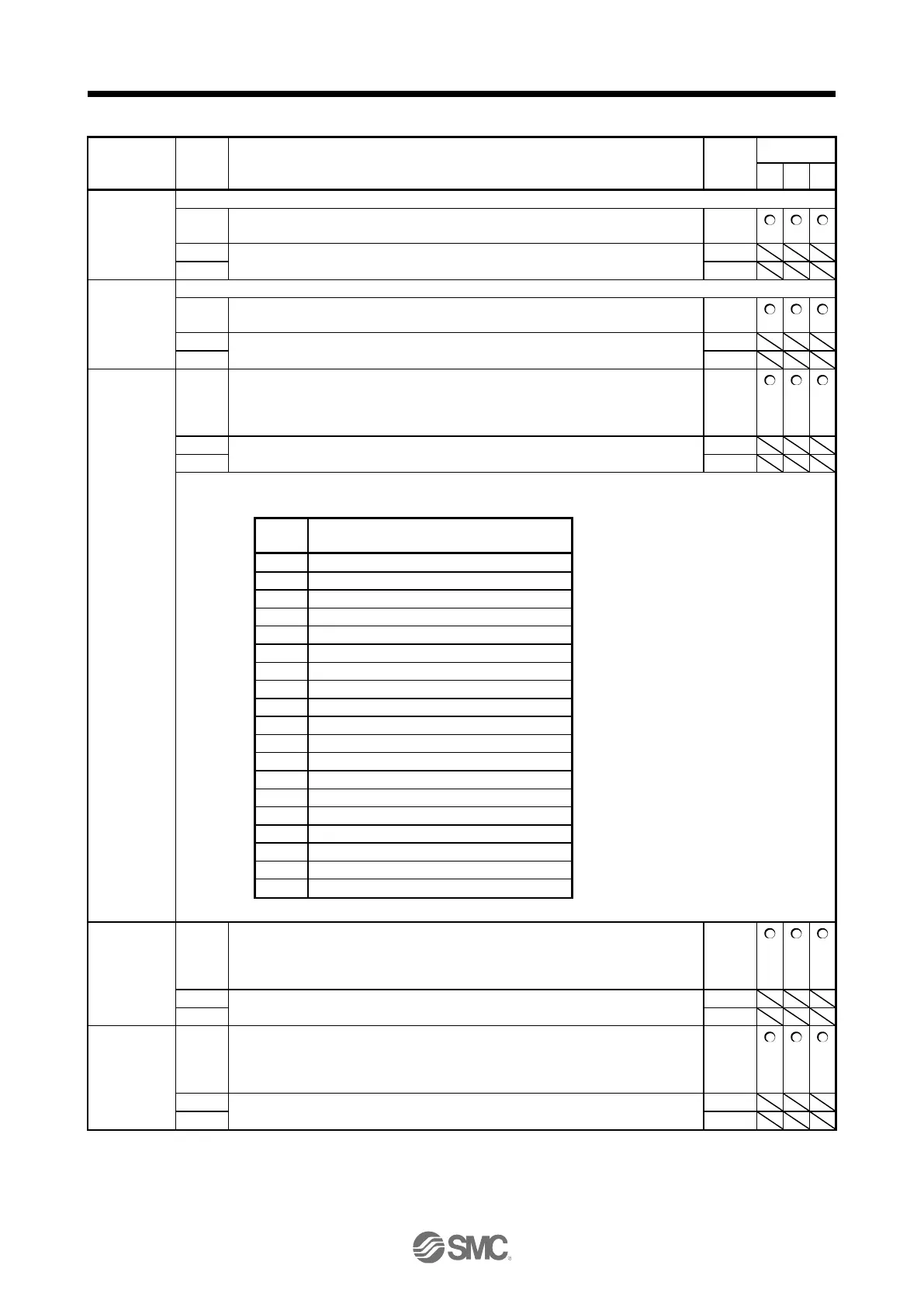
PD07
*DO1
Output device
selection 1
Device selection
Any output device can be assigned to the CN3-13 pin. As the initial value, MBR
(Electromagnetic brake interlock) is assigned to the pin.
Refer to table 5.10 for settings.
Table 5.10 Selectable output devices
MBR (Electromagnetic brake interlock)
DB (Dynamic brake interlock)
ZSP (Zero speed detection)
CDPS (Variable gain selection)
CLDS (During fully closed loop control)
ABSV (Absolute position undetermined)
MTTR (During tough drive)
DOA (General-purpose output A) (Note)
DOB (General-purpose output B) (Note)
DOC (General-purpose output C) (Note)
PD08
*DO2
Output device
selection 2
Device selection
Any output device can be assigned to the CN3-9 pin. INP (In-position) is assigned
as the initial value.
Refer to table 5.10 in [Pr. PD07] for settings.
PD09
*DO3
Output device
selection 3
Device selection
Any output device can be assigned to the CN3-15 pin. ALM (Malfunction) is
assigned as the initial value.
Refer to table 5.10 in [Pr. PD07] for settings.

 Loading...


