16. HOW TO USE THE POINT TABLE
Set the point table values using Setup software (MR Configurator2
TM
) or "Point table 001 to 255".
Set the position data, servo motor speed, acceleration time constant, deceleration time constant, dwell
time, auxiliary function, and M code to the point table.
To use the point table with the absolute position command method, set "0", "1", "8", or "9" to the
auxiliary function. To use the point table with the relative position command method, set "2", "3", "10", or
"11" to the auxiliary function.
When you set a value outside the setting range to the point table, the set value will be clamped with the
maximum or minimum value. If the value becomes out of the range because of the changes in the
command unit or the connected servo motor, [AL. 37] will occur.
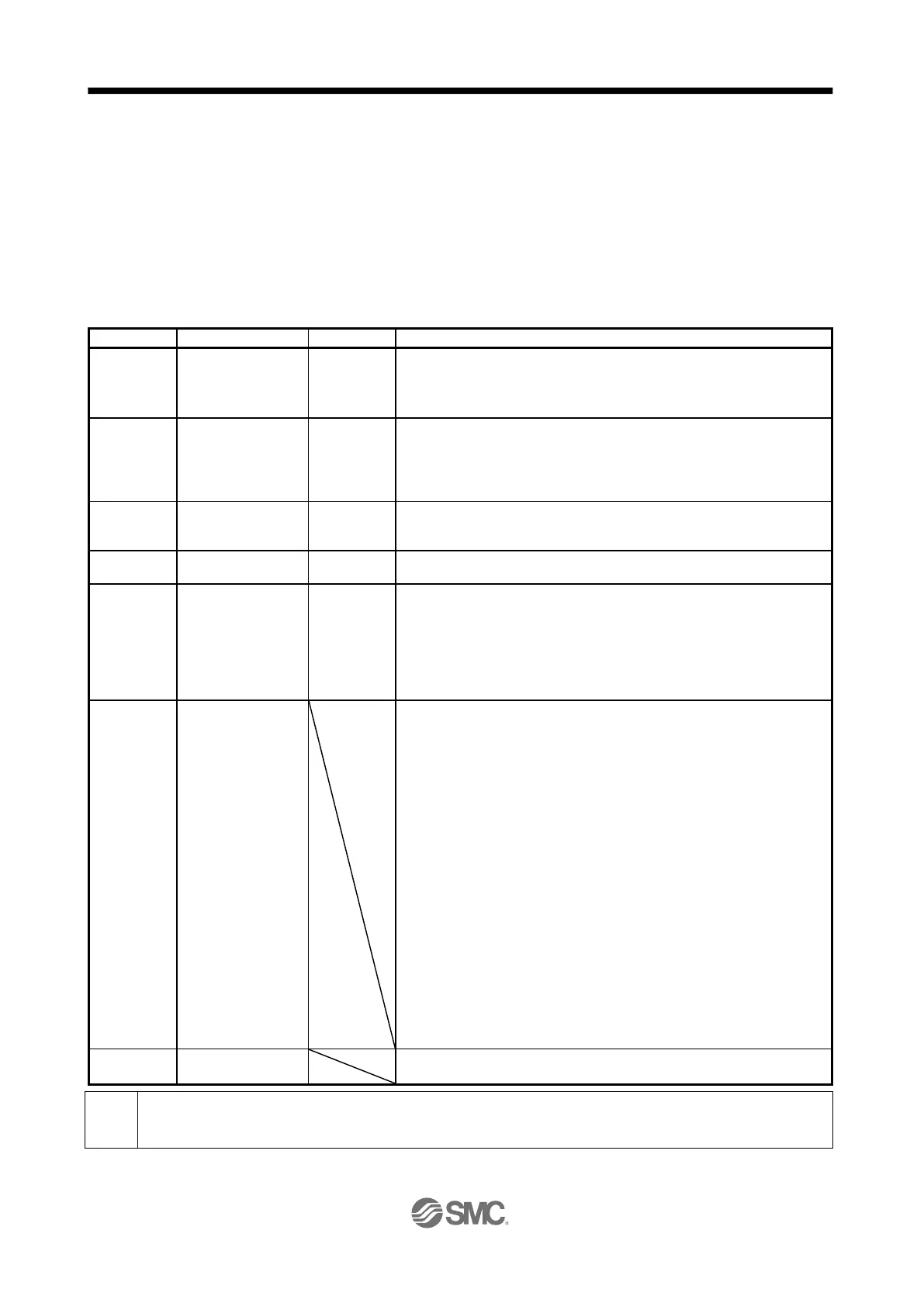
-999999 to 999999
(Note 1)
×10
STM
µm
×10
(STM-4)
inch
pulse
(1) When using this point table with the absolute position command method
Set the target address (absolute value).
(2) When using this point table with the relative position command method
Set the travel distance. A "-" sign indicates a reverse rotation command.
0.01 r/min
0.01 mm/s
(Note 2)
Set the command speed of the servo motor for execution of positioning.
The setting value must be the instantaneous permissible speed or less of the
servo motor used.
If a value smaller than "1" is set for the servo motor speed, the servo motor
may not rotate.
Acceleration
time constant
Set a time for the servo motor to reach the rated speed.
Deceleration
time constant
Set a time for the servo motor to stop from the rated speed.
Set the dwell time.
To disable the dwell time, set "0" or "2" to the auxiliary function.
To perform a continuous operation, set "1", "3", "8", "9", "10", or "11" to the
auxiliary function and "0" to the dwell time.
When the dwell time is set, a positioning of the next point table will be started
after the positioning of the selected data is completed, and the set dwell time
has elapsed.
Set the auxiliary function.
(1) When using this point table with the absolute position command method
0: Automatic operation for a selected point table is performed.
1: Automatic continuous operation is performed without a stop to the next
point table.
8: Automatic continuous operation is performed without a stop to the point
table selected at start-up.
9: Automatic continuous operation is performed without stopping a point
table No. 1.
(2) When using this point table with the relative position command method
2: Automatic operation for a selected point table is performed.
3: Automatic continuous operation is performed without a stop to the next
point table.
10: Automatic continuous operation for a point table selected at start-up is
performed.
11: Automatic continuous operation is performed without stopping a point
table No. 1.
When an opposite rotation direction is set, the servo motor rotates in the
opposite direction after smoothing zero (command output) is confirmed.
Setting "1" or "3" to point table No. 255 results in an error.
Refer to (4) (b) in this section for details.
Set a code to output at the completion of positioning.
M code can be read with "M code actual value".
When the unit of the position data is µm or inch, the location of the decimal point is changed according to the STM setting.
 Loading...


