Phaser 4500/4510 Service Manual 10-5
Wiring Diagrams
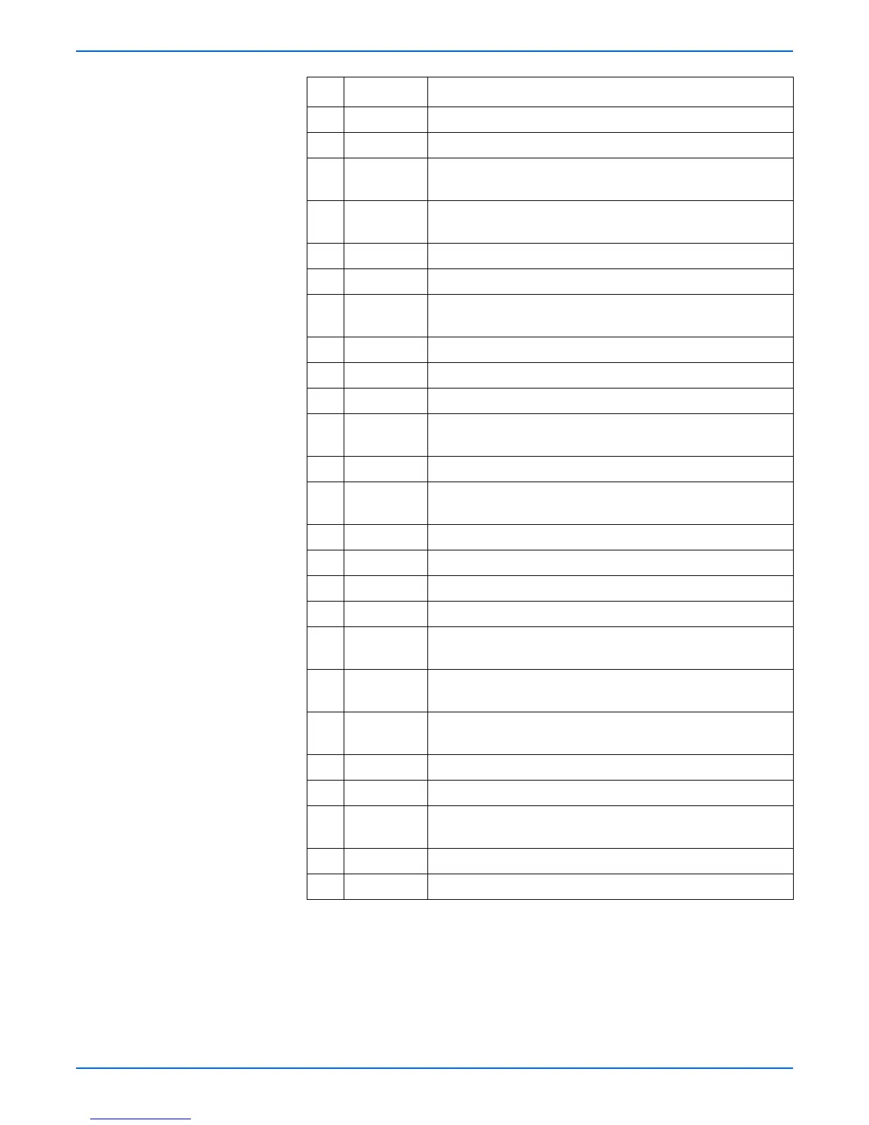
246 O-124 Connects the no paper sensor and tray 2 harness assembly
247 P-125 Connects the tray 2 feed clutch and tray 2 harness assembly
248 N-124 Connects the tray 2 harness assembly and chute harness
assembly
260 O-124 Connects the tray 2 low paper sensor and low paper sensor
harness
270 T-121 Connects the Sub Fan and LVPS harness assembly
271 U-122 Connects LVPS harness assembly and main motor
290 N-121 Connects the output tray full sensor and exit sensor harness
assembly1
310 O-123 Connects the print cartridge and GUIDE Assembly CRU
J310 H-107 P4500 only: Plug on I/P board for Flash Memory option
401 V-122 3.3 VDC Input from the LVPS
402 V-122 P4500 only: 3.3 VDC and 5 VDC Output to the Image Processor
Board
403 V-122 P4500 only: 24 V Input from the LVPS
404 U-122 P4500 only: Connects 24 V from the LVPS to the DC-DC
converter at P403
411 J-106 Connects the top cover switch and LVPS harness
480 V-124 Connects the AC harness to the power switch
J650 I-108 P4510: Plug on the I/P Board for the Hard Drive.
800 H-109 Connects the I/P Board to the HVPS/engine logic board
810 E-107 P4500 only: Connects the control panel and control panel
harness assembly
850 I-109 P4500: Plug on the I/P Board for the Hard Drive.
P4510: Plug on the I/P Board for the Flash Memory option
1821 B-108 Connects the left tray guide assembly and LVPS harness
assembly (size switch connection)
2011 F-108 Connects SOS sensor to Laser Diode board
2083 G-110 Connects the feeder harness 1 and feeder harness 2
2750 R-124 Connects the LVPS harness assembly and duplex unit assembly
harness
3070 N-122 Connects stacker harness 1 and stacker harness 2
4647 R-122 Connects the fuser harness assembly and fuser assembly
P/J Coordinates Remarks

 Loading...


