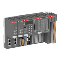
The following figure shows the connection for inputs of the option board for digital I/O extension
TA5110-2DI2DOT:
Sink inputs of TA5110-2DI2DOT Source inputs of TA5110-2DI2DOT
The following figure shows the connection for outputs of the option board for digital I/O exten-
sion TA5110-2DI2DOT:
NOTICE!
Risk of malfunctions in the plant!
Only if L+/M of the CPU is available and the outputs are already configured in
the AB program, the outputs will switch on as soon as the UP/ZP is available.
This must be considered in the application planning.
NOTICE!
Risk of damaging the I/O module!
The outputs are not protected against short circuits and overload.
– Never short-circuit or overload the outputs.
– Never connect the outputs to other voltages.
– Use an external fuse for the outputs.
The module provides several diagnosis functions, see Diagnosis
Ä
“Diagnosis” on page 68.
The meaning of the LEDs is described in the section State LEDs
Ä
“State LEDs” on page 68.
The module itself does not store configuration data. It receives its parameterization data from
the CPU module during power-up of the system.
Hence, replacing optional modules is possible without any re-parameterization via software.
If the external power supply voltage via UP/ZP terminals fails, the I/O module
loses its configuration data. The whole station has to be switched off and on
again to re-configure the module.
I/O configura-
tion
Processor modules > AC500-eCo
2022/01/31 3ADR010278, 3, en_US 67

 Loading...