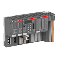
For a detailed description of the mounting, disassembly and connection of the
module, please refer to the System Assembly, Construction and Connection
chapter
Ä
Chapter 2.6 “AC500 (Standard)” on page 971.
The terminals 1.8 and 2.8 as well as 1.9, 2.9 and 3.9 are electrically interconnected within the
terminal unit and have always the same assignment, independent of the inserted module:
Terminals 1.8 and 2.8: Process supply voltage UP = +24 V DC
Terminal 3.8: Process supply voltage UP3 = +24 V DC
Terminals 1.9, 2.9 and 3.9: Process supply voltage ZP = 0 V
With a separate UP3 power supply, the digital outputs can be switched off
externally. This way, an emergency-off functionality can be realized.
Conditions for undisturbed operating with older I/O expansion modules
All I/O expansion modules that are attached to the CI52x-MODTCP must be
powered up together with the CI52x-MODTCP if the firmware version of these
I/O expansion modules is V1.9 or lower.
The firmware version is related to the index. The index is printed on the module type label on
the right side.
Modules as of index listed in the following table can be powered up independently.
S500 I/O module type First index with firmware version above 1.9
AI523 D0
AI523-XC D0
AI531 A3
AI531-XC A0
AO523 D0
AO523-XC D0
AX521 D0
AX521-XC D0
AX522 D0
AX522-XC D0
CD522 A2
CD522-XC A0
DA501 A2
DA501-XC A0
DA502 A1
DA502-XC A1
DC522 D0
DC522-XC D0
DC523 D0
Communication interface modules (S500) > Modbus
2022/01/313ADR010278, 3, en_US732

 Loading...