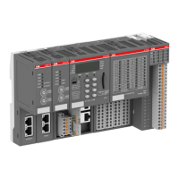
S500 I/O module type First index with firmware version above 1.9
DC523-XC D0
DC532 D0
DC532-XC D0
DI524 D0
DI524-XC D0
DO524 A2
DO524-XC A2
DX522 D0
DX522-XC D0
DX531 D0
AC522 D0
PD501 D0
Do not connect any voltages externally to digital outputs!
Reason: Externally voltages at an output or several outputs may cause that
other outputs are supplied through that voltage instead of voltage UP3 (reverse
voltage). This ist not intended usage.
CAUTION!
Risk of malfunction by unintended usage!
If the function cut-off of the digital outputs is to be used by deactivation of the
supply voltage UP3, be sure that no external voltage is conncted at the outputs
DO0..DO7.
The assignment of the other terminals:
Terminal Signal Description
1.0 AI0+ Positive pole of analog input signal 0
1.1 AI1+ Positive pole of analog input signal 1
1.2 AI2+ Positive pole of analog input signal 2
1.3 AI3+ Positive pole of analog input signal 3
1.4 AI- Negative pole of analog input signals 0 to 3
1.5 AO0+ Positive pole of analog output signal 0
1.6 AO1+ Positive pole of analog output signal 1
1.7 AI- Negative pole of analog output signals 0 and 1
1.8 UP Process voltage UP (24 V DC)
1.9 ZP Process voltage ZP (0 V DC)
2.0 DI0 Signal of the digital input DI0
2.1 DI1 Signal of the digital input DI1
2.2 DI2 Signal of the digital input DI2
2.3 DI3 Signal of the digital input DI3
2.4 DI4 Signal of the digital input DI4
Communication interface modules (S500) > Modbus
2022/01/31 3ADR010278, 3, en_US 733

 Loading...