MPC5553/MPC5554 Microcontroller Reference Manual, Rev. 5
25-2 Freescale Semiconductor
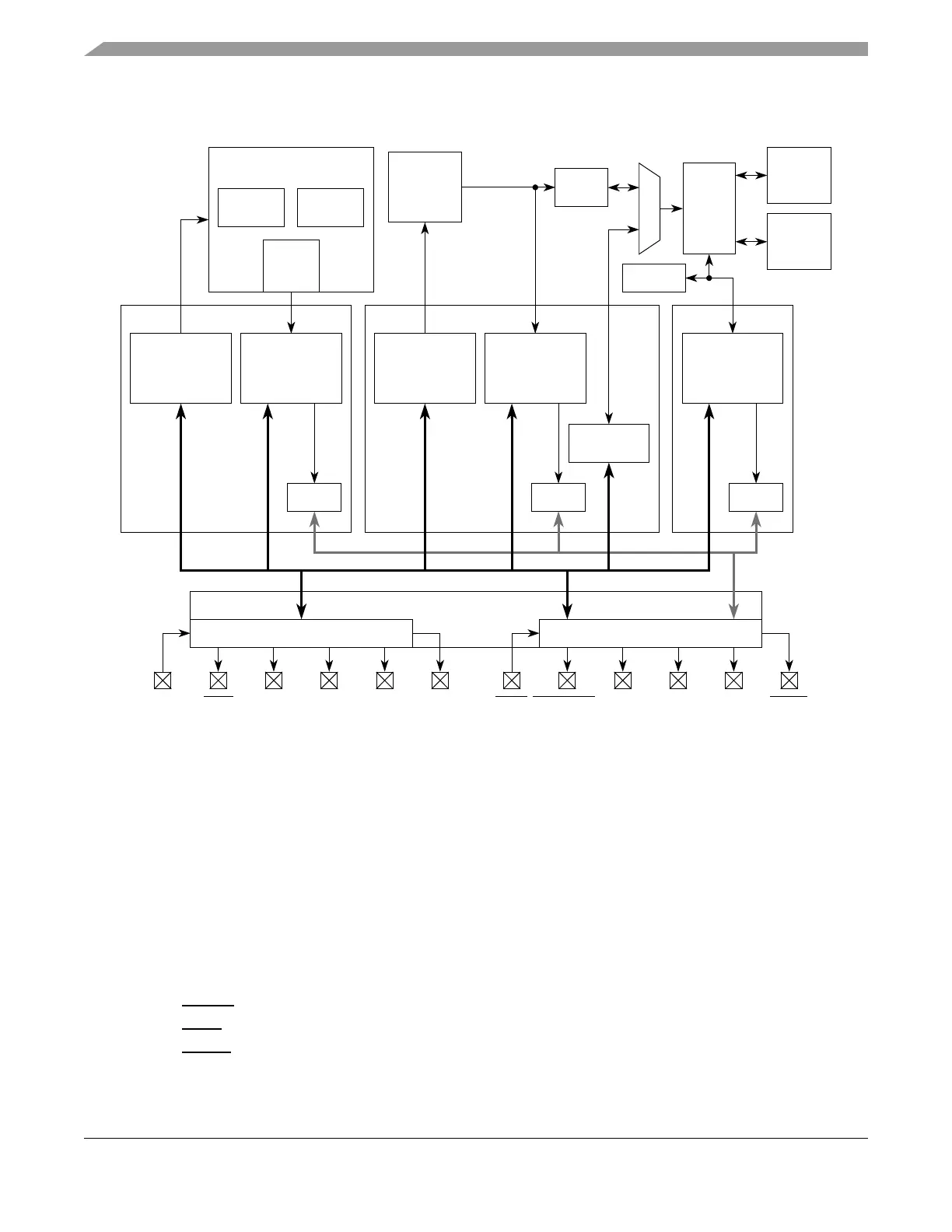
25.1.1 Block Diagram
Figure 25-1. NDI Block Diagram
25.1.2 Features
The NDI module is compliant with the IEEE-ISTO 5001-2003 standard. The following features are
implemented:
• 15 or 23 bit full-duplex pin interface for medium and high visibility throughput.
• One of two modes selected by register configuration: full port mode (FPM) and reduced port mode
(RPM). FPM comprises 12 MDO pins, and RPM comprises 4 MDO pins.
• Auxiliary output port.
— 1 MCKO (message clock out) pin
— 4 or 12 MDO (message data out) pins
—2 MSEO
(message start/end out) pins
—1 RDY (ready) pin
—1 EVTO (event out) pin
JCOMP
Program, Data,
Ownership,
Watchpoint,
Trace
R/W Register,
Halt, Step,
Continue
Data,
Watchpoint,
Trace
Buffer
Program, Data,
Ownership,
Watchpoint,
Trace
R/W Register,
R/W Data,
Halt, Step,
Continue
Read/Write
Access
Buffer
NZ6C3
Nexus Port Controller
(NPC)
JTAG Port Controller
RDY TDI TCK TDO TMS EVTI
Auxiliary Port
MSEO[0:1] MCKO MDO(4 or 12) EVTO
• • •
Buffer
On-Chip
Memory
and I/O
Off-Chip
Memory
and I/O
XBAR
eDMAC
MMU
Cache
e200z6
Engine
1
CDC
Engine
2 *
eTPU
NXDMNDEDI
* The MPC5553 has only one eTPU engine; the MPC5554 has two eTPU engines.