MPC5553/MPC5554 Microcontroller Reference Manual, Rev. 5
14-2 Freescale Semiconductor
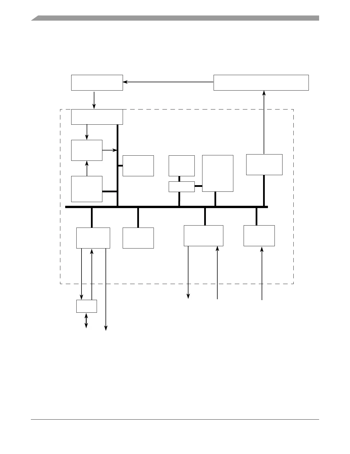
14.1.1 Block Diagram
The block diagram of the FEC is shown below. The FEC is implemented with a combination of hardware
and microcode. The off-chip (Ethernet) interfaces are compliant with industry and IEEE 802.3 standards.
Figure 14-1. FEC Block Diagram
Slave Interface
CSR
FIFO
DMA
Descriptor
Controller
MII
Receive
Tran smi t
Bus
Controller
Controller
FEC_MDCFEC_MDIO
FEC_RX_CLK
FEC_RX_DV
FEC_RXD[3:0]
FEC_RX_ER
FEC_TX_CLKFEC_TX_EN
FEC_TXD[3:0]
FEC_TX_ER
FEC_CRS
MIB
(RISC +
microcode)
I/O
PAD
Counters
MII/7-WIRE DATA
OPTION
RAM
RAM I/F
FEC Bus
System Bus Crossbar Switch (XBAR)PBRIDGE_B
Master
FEC Block
MDO
MDEN
MDI
FEC_COL