MPC5553/MPC5554 Microcontroller Reference Manual, Rev. 5
Freescale Semiconductor B-3
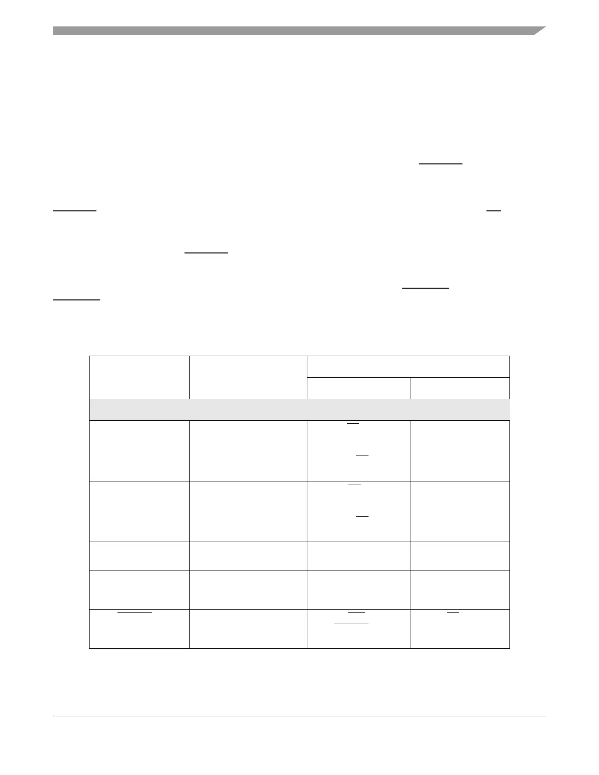
B.2 Calibration Bus
The calibration bus is made up of address bus, data bus, bus control and clock signals, and is used by any
tool that includes additional memory to hold calibration data or other code or data being developed. See
Table B-1 for calibration bus signals. A 16-bit calibration data bus and a 19- to 21-bit calibration address
bus is included giving a basic addressing range of 1 MByte. Alternatively, the maximum memory
addressable using just one chip select is 4 Mbytes. Refer to Table B-2.
The VertiCal connector supports up to 4 chip selects signals, although the actual number of chip selects
available depends on which device of the MPC5500 family is used. The CAL_CS[0] chip select is
available for most MPC5500 devices, and should be used as the default chip select for calibration use to
ensure maximum portability of calibration tools across devices. These additional chip selects signals are
configured and function like the non-calibration chip selects. In the MPC5553, the calibration chip selects
CAL_CS[n], have a higher priority in address decoding than the non-calibration chip selects, CS[n]. Refer
to Section B.6, “Application Information,” for application information on the number of calibration chip
selects.
The calibration chip selects CAL_CS[n] also have alternate functions as additional address bits, allowing
a flexible choice between increased addressing range or increased chip select availability. Devices that
support less than 4 calibration chip selects are designed to support this means of extending the contiguous
calibration addressing range by omitting chip selects starting from CAL_CS[1]. For this reason
CAL_CS[1] is selected as the single unimplemented chip select on the MPC5553.
Table B-1. Calibration Bus Signals
VertiCal Signal Name Function
Device Implementation Signal Name
MPC5553 MPC5554
Address/Data Bus
CAL_ADDR[10] Address bus BR
1
_
CAL_ADDR[10]_
FEC_MDC_
CAL_CS
[2]_
GPIO[72]
—
CAL_ADDR[11] Address bus BG
1
_
CAL_ADDR[11]_
FEC_MDIO_
CAL_CS
[3]_
GPIO[73]
—
CAL_ADDR[12:26] Address bus ADDR[12:26]_
GPIO[8:22]
ADDR[12:26]_
GPIO[8:22]
CAL_ADDR[27:30] Address bus ADDR[8:11]_
CAL_ADDR[27:30]_
GPIO[4:7]
ADDR[27:30]_
GPIO[23:26]
CAL_CS
[0] Chip Select TEA_
C
AL_CS[0]_
GPIO[71]
CS
[0]_
ADDR[8]_
GPIO[0]