MPC5553/MPC5554 Microcontroller Reference Manual, Rev. 5
Freescale Semiconductor 2-61
2.4 eTPU Pin Connections and Serialization
2.4.1 ETPUA[0:15]
The ETPUA[0:15] module channels connect to external pins or may be serialized out through the DSPI C
module. A diagram for the ETPUA[0:15] to SOUTC connection is given in Figure 2-5. The full list of
connections is given in Table 2-5. Although not shown in Figure 2-5, the output channels of
ETPUA[12:15] are connected to the ETPUA[0:3]_ETPUA[12:15]_GPIO[114:117] pins.
The eTPU TCRA clock input is connected to an external pin only.
V
DDSYN
3.3 V XTAL, EXTAL_EXTCLK
V
RC33
3.3 V V
RCCTL
Other Power Segments
V
PP
4.5–5.25 V
4
—
V
FLASH
3.0–3.6 V —
V
DD33
3.0–3.6 V —
V
STBY
0.9–1.1 V —
1
These are nominal voltages. V
DDE
is 1.62–3.6 V; V
DDEH
is 3.0–5.5 V. All V
DDE
voltages are 10%; V
DDEH
voltages are
+5%/–10%.V
RC33
is 10%; V
DDSYN
is 10%; V
DDA1
is + 5%, –10%.
2
When the PLL is configured for external reference mode, the V
DDE5
supply affects the acceptable signal levels for the external
reference. Refer to Section 11.1.4.2, “External Reference Mode.”
3
V
DDE2
and V
DDE3
are separate segments in the MPC5554 pad ring. These segments are shorted together in the package
substrate. The following pins are part of the V
DDE3
segment: DATA[0:31], GPIO[206:207], BR, BB, BG, and OE.
4
During read operations, V
PP
can be as high as 5.3 V or as low as 3.0 V.
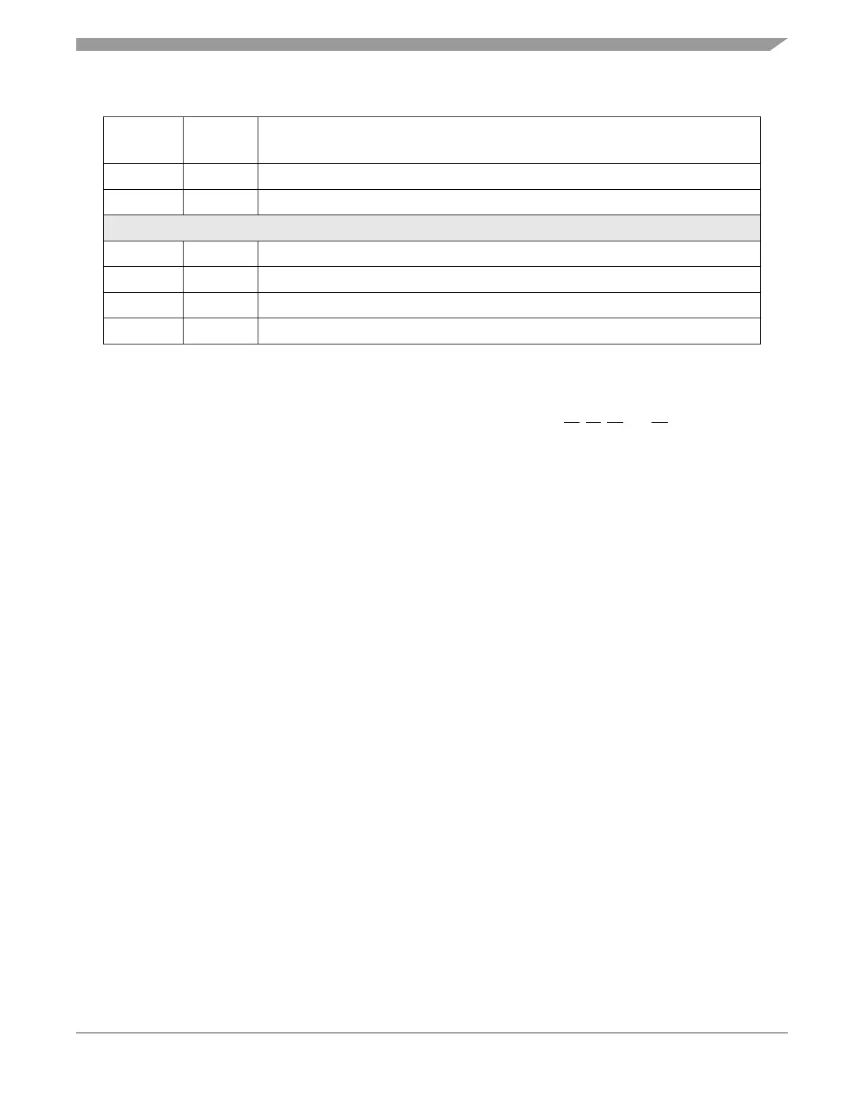
Table 2-4. MPC5554 Power/Ground Segmentation (Continued)
Power
Segment
Voltage
1
I/O Pins Powered by Segment