MPC5553/MPC5554 Microcontroller Reference Manual, Rev. 5
20-62 Freescale Semiconductor
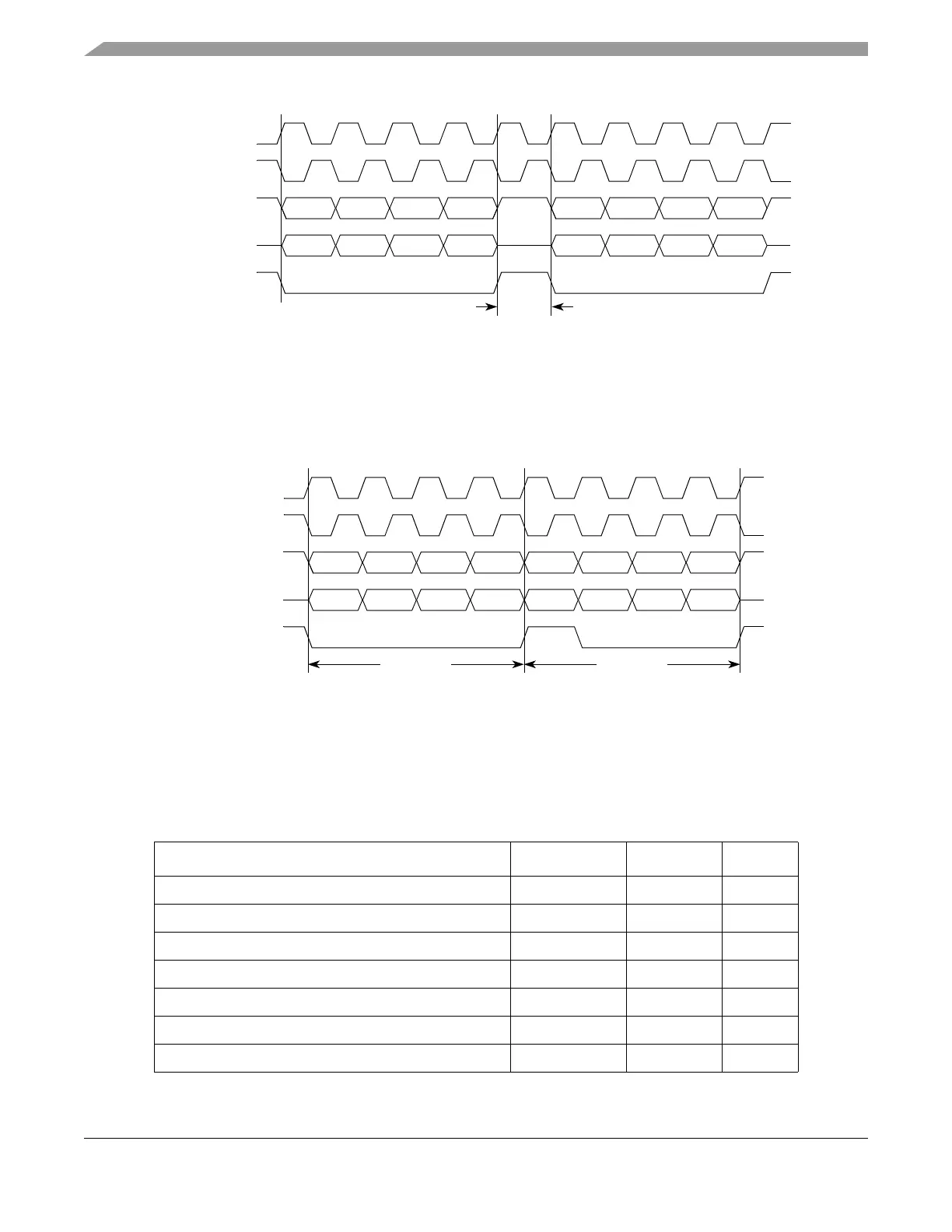
Figure 20-43. Continuous SCK Timing Diagram (CONT=0)
If the CONT bit in the TX FIFO entry is set or the DCONT in the DSPIx_DSICR is set, PCS remains
asserted between the transfers when the PCS signal for the next transfer is the same as for the current
transfer. Figure 20-44 shows timing diagram for continuous SCK format with continuous selection
enabled.
Figure 20-44. Continuous SCK Timing Diagram (CONT=1)
20.4.9 Interrupts/DMA Requests
The DSPI has five conditions which can only generate interrupt requests and two conditions that can
generate interrupt or DMA request. Table 20-30 lists the six conditions.
Table 20-30. Interrupt and DMA Request Conditions
Condition Flag Interrupt DMA
End of transfer queue has been reached (EOQ) EOQF X
TX FIFO is not full TFFF X X
Current frame transfer is complete TCF X
TX FIFO underflow has occurred TFUF X
RX FIFO is not empty RFDF X X
RX FIFO overflow has occurred RFOF X
A FIFO overrun has occurred
1
TFUF OR RFOF X
SCK
(CPOL = 0)
PCS
SCK
(CPOL = 1)
Master SOUT
t
DT
t
DT
= 1 SCK.
Master SIN
SCK
(CPOL = 0)
PCS
SCK
(CPOL = 1)
Master SOUT
Master SIN
Transfer 1 Transfer 2