MPC5553/MPC5554 Microcontroller Reference Manual, Rev. 5
Freescale Semiconductor 19-9
19.3 Memory Map/Register Definition
This section provides memory maps and detailed descriptions of all registers. Data written to or read from
reserved areas of the memory map is undefined.
19.3.1 eQADC Memory Map
This section provides memory maps for the eQADC.
ETRIG1/
GPIO112
External trigger for CFIFO1,
CFIFO3, and CFIFO5/
GPIO
I
I/O
— / Up — / Up Digital 416
Power Supplies
VRH Voltage Reference High I — / — VRH Power 416
324
208
VRL Voltage Reference Low I — / — VRL Power 416
324
208
REFBYPC Reference Bypass Capacitor Input I — / — REFBYPC Power 416
324
208
V
DDA
Analog Positive Power Supply I — — Power 416
324
208
V
SSA
Analog Negative Power Supply I — — Power 416
324
208
1
Terminology is O — output, I — input, Up — weak pullup enabled, Down — weak pulldown enabled, Low — output driven
low, High — output driven high. A dash on the left side of the slash denotes that both the input and output buffers for the
pin are off. A dash on the right side of the slash denotes that there is no weak pull up/down enabled on the pin. The signal
name to the left or right of the slash indicates the pin is enabled.
2
Function after reset of GPI is general-purpose input. A dash on the left side of the slash denotes that both the input and
output buffers for the pin are off. A dash on the right side of the slash denotes that there is no weak pull up/down enabled
on the pin.
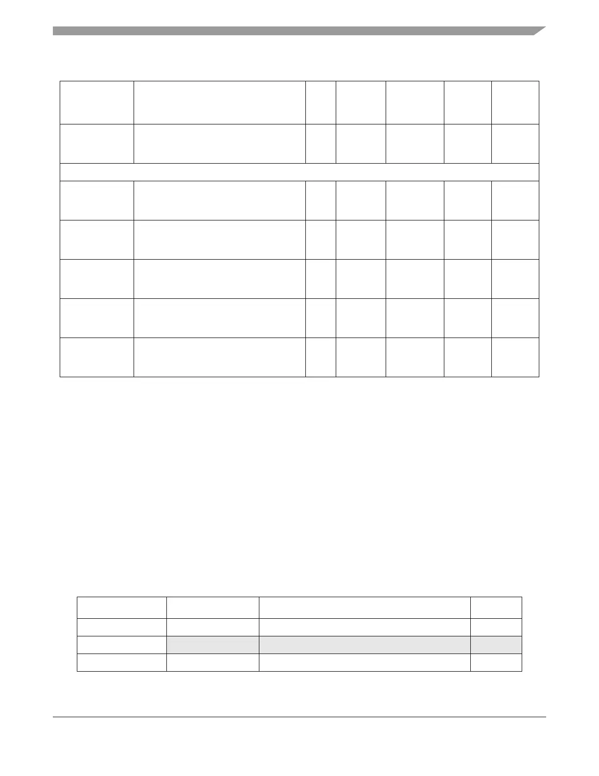
Table 19-2. eQADC Memory Map
Address Register Name Register Description Size (bits)
Base (0xFFF8_0000) EQADC_MCR EQADC module configuration register 32
Base + 0x0004 — Reserved —
Base + 0x0008 EQADC_NMSFR eQADC null message send format register 32
Table 19-1. eQADC External Signals (Continued)
Function Description
I/O
Type
Status
During
Reset
1
Status
After
Reset
2
Type Package