MPC5553/MPC5554 Microcontroller Reference Manual, Rev. 5
14-34 Freescale Semiconductor
14.4 Functional Description
This section describes the operation of the FEC, beginning with the hardware and software initialization
sequence, then the software (Ethernet driver) interface for transmitting and receiving frames.
Following the software initialization and operation sections are sections providing a detailed description
of the functions of the FEC.
14.4.1 Initialization Sequence
This section describes which registers are reset due to hardware reset, which are reset by the FEC RISC,
and what locations the user must initialize prior to enabling the FEC.
14.4.1.1 Hardware Controlled Initialization
In the FEC, registers and control logic that generate interrupts are reset by hardware. A hardware reset
deasserts output signals and resets general configuration bits.
Other registers reset when the ECR[ETHER_EN] bit is cleared. ECR[ETHER_EN] is deasserted by a hard
reset or may be deasserted by software to halt operation. By deasserting ECR[ETHER_EN], the
configuration control registers such as the TCR and RCR will not be reset, but the entire data path will be
reset.
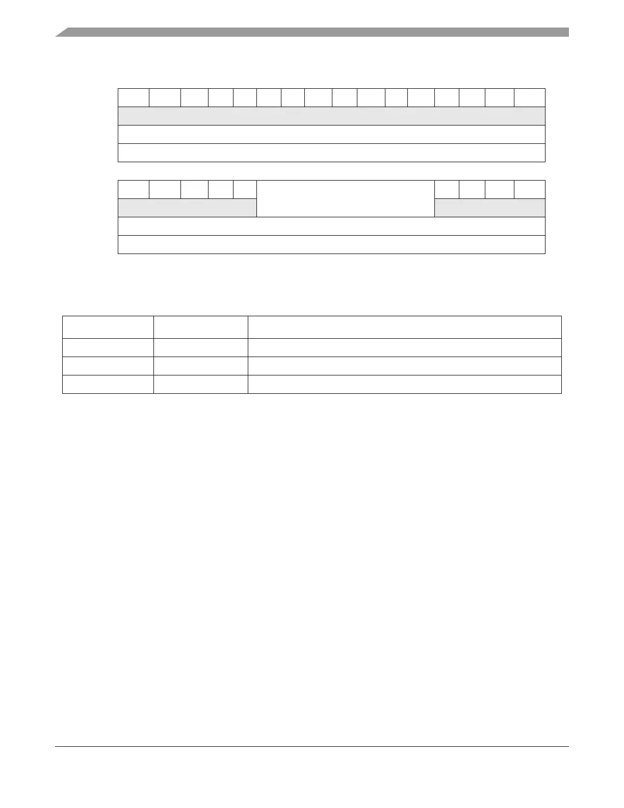
0 1 2 3456 7 8 91011121314 15
R0 0 0 0 0 0 0 0 0 0 0 0 0 0 0 0
W
Reset U U U U U U U U U U U U U U U U
Address Base + 0x0188
16 17 18 19 20 21 22 23 24 25 26 27 28 29 30 31
R0 0 0 0 0 R_BUF_SIZE 0 0 0 0
W
Reset U U U U U U U U U U U U U U U U
Address Base + 0x0188
1
“U” signifies a bit that is uninitialized.
Figure 14-25. Receive Buffer Size Register (EMRBR)
Table 14-28. EMRBR Field Descriptions
Bits Name Descriptions
0–20 — Reserved, should be written to 0 by the host processor.
21–27 R_BUF_SIZE Receive buffer size.
28–31 — Reserved, should be written to 0 by the host processor.