MPC5553/MPC5554 Microcontroller Reference Manual, Rev. 5
20-50 Freescale Semiconductor
(MPC5553) master that a trigger condition has occurred. When an on-chip DSPI slave has a change in data
to be serialized it can assert the MTRIG signal to the DSPI master which initiates the transfer. When a
DSPI slave has its ht signal asserted it will assert its MTRIG signal thereby propagating trigger signals
from other DSPI slaves to the DSPI master.
The MTOCNT field in the DSPIx_DSICR must be written with the total number of bits to be transferred.
The MTOCNT field must equal the sum of all FMSZ fields in the selected DSPIx_CTARs for the DSPI
master and all DSPI slaves. For example if one 16-bit DSI frame is created by concatenating 8 bits from
the DSPI master, and 4 bits from each of the DSPI slaves in Figure 20-29, the DSPI master’s frame size
must be set to eight in the FMSZ field, and the DSPI slaves’ frame size must be set to four. The largest DSI
frame supported by the MTOCNT field is 64 bits (MPC5554) or 48 bits (MPC5553). Any number of
DSPIs can be connected together to concatenate DSI frames, as long as each DSPI transfers a minimum
of 4 bits and a maximum of 16 bits and the total size of the concatenated frame is less than or equal to 64
bits long (MPC5554) or 48 bits (MPC5553).
20.4.5 Combined Serial Interface (CSI) Configuration
In master mode, the CSI configuration of the DSPI is used to support SPI and DSI functions on a frame by
frame basis. CSI configuration allows interleaving of DSI data frames from the parallel input signals (from
the eTPU or eMIOS) with SPI commands and data from the TX FIFO. The data returned from the bus slave
is either used to drive the parallel output signals (to the eTPU or eMIOS) or is stored in the RX FIFO. CSI
configuration allows serialized data and configuration or diagnostic data to be transferred to a slave device
using only one serial link. The DSPI is in CSI configuration when the DCONF field in the DSPIx_MCR
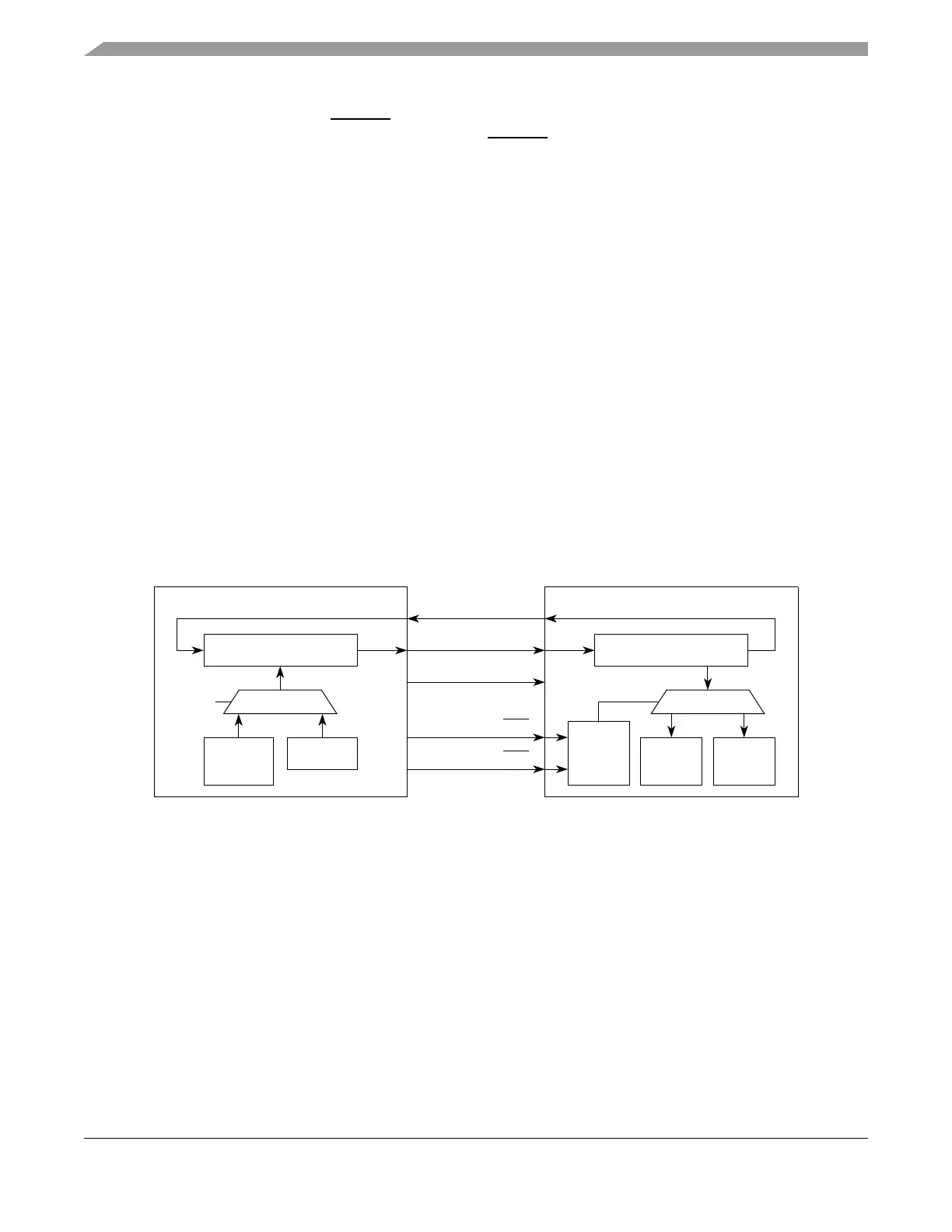
is 0b10. Figure 20-31 shows an example of how a DSPI can be used with a deserializing peripheral that
supports SPI control for control and diagnostic frames.
Figure 20-31. Example of System using DSPI in CSI Configuration
In CSI configuration the DSPI transfers DSI data based on Section 20.4.4.5, “DSI Transfer Initiation
Control.” When there are SPI commands in the TX FIFO, the SPI data has priority over the DSI frames.
When the TX FIFO is empty, DSI transfer resumes.
Two peripheral chip select signals indicate whether DSI data or SPI data is transmitted. The user must
configure the DSPI so that the two CTARs associated with DSI data and SPI data assert different peripheral
chip select signals denoted in the figure as PCSx and PCSy. The CSI configuration is only supported in
master mode.
Data returned from the external slave while a DSI frame is transferred is placed on the parallel output
signals. Data returned from the external slave while an SPI frame is transferred is moved to the RX FIFO.
The TX FIFO and RX FIFO are fully functional in CSI mode.
SPI
DSPI Master
DSI
Shift Register
TX FIFO
TX
Priority
Control
SIN
SOUT
SCK
PCSx
PCSy
SPI
External Slave Deserializer
Shift Register
Frame
Frame
Select
Logic
SOUT
SIN
SCK
SSx
SSy
DSI
Frame