MPC5553/MPC5554 Microcontroller Reference Manual, Rev. 5
12-2 Freescale Semiconductor
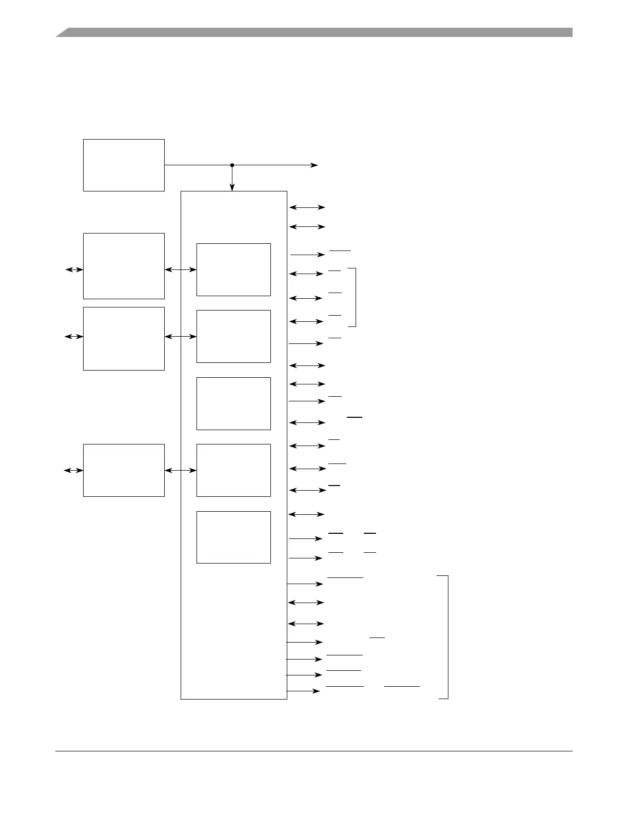
12.1.1 Block Diagram
Figure 12-1 is a block diagram of the EBI. The signals shown are external pins to the MCU. All signals
are implemented in the MPC5554 and in the 416 and 324 BGA of the MPC5553 except where noted. The
MPC5553 208 BGA does not have EBI signals pinned out.
Figure 12-1. EBI Block Diagram
External Bus
Interface
Memory
Controller
External Master
Controller
Bus
Monitor
Registers
Arbiter
Slave
Interface/
CLKOUT Driver
CLKOUT
Crossbar Switch
(XBAR)
Master
Interface/
Crossbar Switch
(XBAR)
Peripheral
Bridge
ADDR[8:11]
DATA[0:31]
CS
[0:3]
TS
WE[0:3]/BE[0:3]
OE
TSIZ[0:1]
RD_WR
BDIP
TA
TEA
BR
BG
BB
ADDR[12:31] (416 BGA of MPC5553 and MPC5554
(MPC5554 only)
DATA[0:15]
(416 BGA of MPC5553 and MPC5554)
(416 BGA of MPC5553 and MPC5554)
WE
[0:1]/BE[0:1]
(MPC5554 only)
(PBridge_A)
(416 BGA of MPC5553 and MPC5554)
(324 BGA of MPC5553)
(416 BGA of MPC5553 and MPC5554)
System Bus
System Bus
and 324 BGA of MPC5553)
CAL_CS[0,2:3]
CAL_DATA[0:15]
CAL_ADDR[10:30]
CAL_OE
CAL_RD_WR
CAL_TS
CAL_WE[0:1]/CAL_BE[0:1]
(324 BGA of MPC5553)
Calibration bus
Note: No external bus pins
are present for the 208
package of the MPC5553.
 Loading...