MPC5553/MPC5554 Microcontroller Reference Manual, Rev. 5
Freescale Semiconductor 1-25
1.8 Revision History
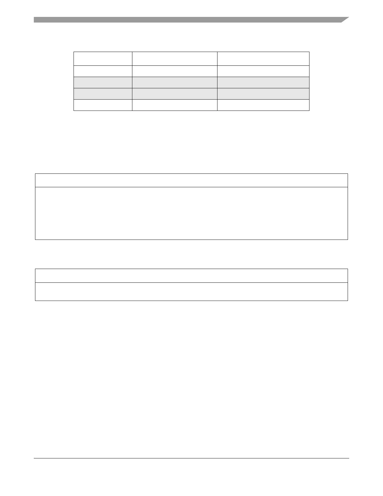
0xC3F0_0000 1 Mbytes Bridge A peripherals
0xC400_0000 (1024 Mbytes–128 Mbytes) Reserved
0xFC00_0000 63 Mbytes Reserved
0xFFF0_0000 1 Mbyte Bridge B Peripherals
1
By using the 4 chip select signals, 32 Mbytes of external memory can be accessed by the
master in a multi-master system.
Table 1-6. Changes to MPC5553/5554 RM for Rev. 4.0 Release
Description of Change
• Added wording for Power Architecture throughout chapter. Removed PowerPC terminology.
• In Features List, added section for Calibration interface
• In Features List, beefed up the section titled “MPC5553-Specific Modules” by adding more information about the FEC.
• In the MPC5553-Specific Modules section, added a section titled “Calibration Bus”
• In the Detailed Features section, beefed up the section titled FEC (MPC5553 Only).
• In the MPC5500 Family Master Memory Map (Multi-Master Mode) table, corrected SRAM values to 64 Kbytes from 96
Kbytes.
Table 1-7. Changes to MPC5553/5554 RM for Rev. 5.0 Release
Description of Change
• In table 1-2, in the address range 0x0100_0000–0x1FFF_FFFF(emulation mapping of FLASH Array), updated the Used
Size (bytes) cell as “2 Mbytes (MPC5554) and 1.5 Mbytes (MPC5553)”.
Table 1-5. MPC5500 Family Master Memory Map (Multi Master Mode) (Continued)
Base Address Size (bytes) Use