MPC5553/MPC5554 Microcontroller Reference Manual, Rev. 5
3-8 Freescale Semiconductor
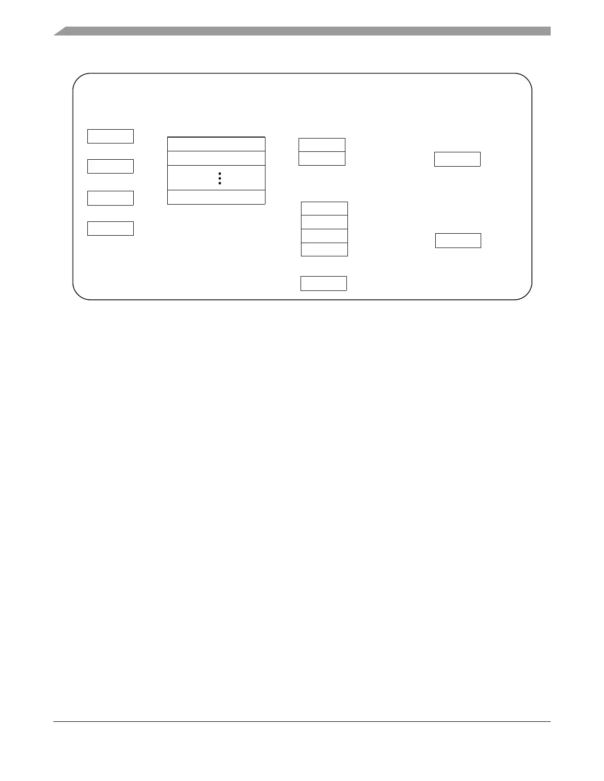
Figure 3-3. User Mode Programmer’s Model
3.2.1 Power Architecture Registers
e200z6 supports most of the registers defined by the Power Architecture embedded category. Notable
exceptions are the floating point registers FPR0-FPR31 and FPSCR. The e200z6 does not support the
Power Architecture floating point architecture in hardware. The supported Power Architecture embedded
category registers are described as follows:
3.2.1.1 User-Level Registers
The user-level registers can be accessed by all software with either user or supervisor privileges. They
include the following:
• General-purpose registers (GPRs). The thirty-two 64-bit GPRs (GPR0–GPR31) serve as data
source or destination registers for integer and SPE APU instructions and provide data for
generating addresses. Power Architecture embedded category instructions affect only the lower 32
bits of the GPRs. SPE APU instructions are provided which operate on the entire 64-bit register.
• Condition register (CR). The 32-bit CR consists of eight 4-bit fields, CR0–CR7, that reflect results
of certain arithmetic operations and provide a mechanism for testing and branching.
The remaining user-level registers are SPRs. Note that the Power Architecture provides the mtspr
and mfspr instructions for accessing SPRs.
• Integer exception register (XER). The XER indicates overflow and carries for integer operations.
• Link register (LR). The LR provides the branch target address for the branch conditional to link
register (bclr, bclrl) instructions, and is used to hold the address of the instruction that follows a
branch and link instruction, typically used for linking to subroutines.
• Count register (CTR). The CTR holds a loop count that can be decremented during execution of
appropriately coded branch instructions. The CTR also provides the branch target address for the
branch conditional to count register (bcctr, bcctrl) instructions.
• The time base facility (TB) consists of two 32-bit registers: time base upper (TBU) and time base
lower (TBL). These two registers are accessible in a read-only fashion to user-level software.
USER Mode Programmer’s Model
GPR0
GPR1
GPR31
General Purpose Registers
General Registers
Condition Register
CR
Count Register
SPR 9CTR
Link Register
SPR 8LR
XER
SPR 1
XER
Timers
Time Base (read-only)
TBL
SPR 268
TBU
SPR 269
SPRG4
SPRG5
SPRG6
SPRG7
SPR 260
SPR 261
SPR 262
SPR 263
SPR General (read-only)
User SPR
USPRG0
SPR 256
Control Registers
Cache Registers
Cache Configuration
(read-only)
L1CFG0
SPR 515
APU Registers
SPE APU Status
and Control Register
SPEFSCR
SPR 512