MPC5553/MPC5554 Microcontroller Reference Manual, Rev. 5
18-2 Freescale Semiconductor
• I/O channel pairs may be shared on a common pin. The output buffer enable (OBE) is not used in
the MPC5553/MPC5554. The outputs are enabled in the SIU; refer to Chapter 6, “System
Integration Unit (SIU).”
Because of the above differences between the MPC5553/MPC5554’s implementation of the eTPU and the
full eTPU, full register bit descriptions are included within this chapter as well as in the Enhanced Time
Processing (eTPU) Reference Manual.
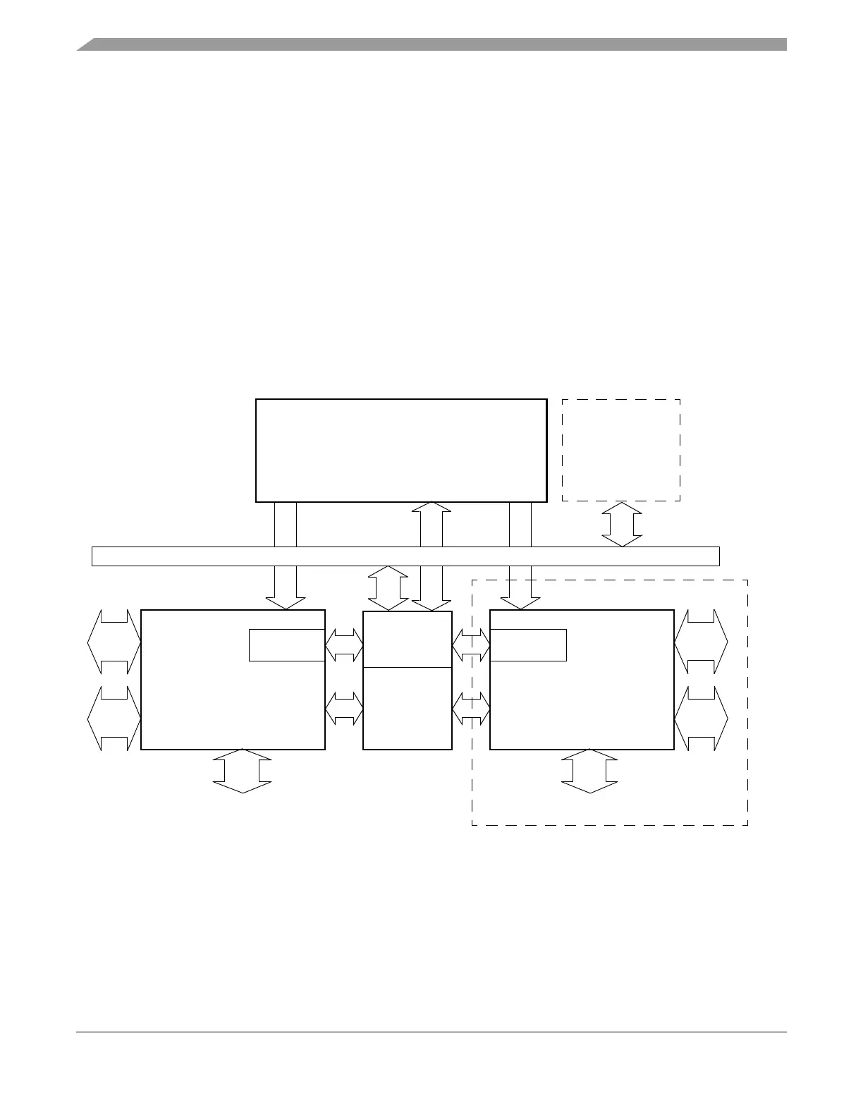
18.1.2 Block Diagram
Figure 18-1 shows a top-level eTPU block diagram. It displays the MPC5554’s dual eTPU engine
configuration.
NOTE
The MPC5553 has a single eTPU engine configuration, and the MPC5554
has two.
Figure 18-1. eTPU Block Diagram
eTPU Engine B*eTPU Engine A
Shared
Data Memory
Slave Interface
Shared Code Memory
Shared
BIU
RegistersRegisters
SCM
Host Core
Debug
eTPU_A Ch. 0–31
STAC
Interface
STAC
Interface
Interface
Debug
Interface
eTPU_B Ch. 0–31
* Only the MPC5554 Contains eTPU_B
(16 Kbytes in the MPC5554,
12 Kbytes in the MPC5553)
(SPRAM)