MPC5553/MPC5554 Microcontroller Reference Manual, Rev. 5
21-20 Freescale Semiconductor
configures the eSCI for 8-bit data characters. A frame with eight data bits has a total of 10 bits. Setting the
M bit configures the eSCI for 9-bit data characters. A frame with nine data bits has a total of 11 bits.
When the eSCI is configured for 9-bit data characters, the ninth data bit is the T8 bit in the eSCI data
register (ESCIx_DR). It remains unchanged after transmission and can be used repeatedly without
rewriting it. A frame with nine data bits has a total of 11 bits.
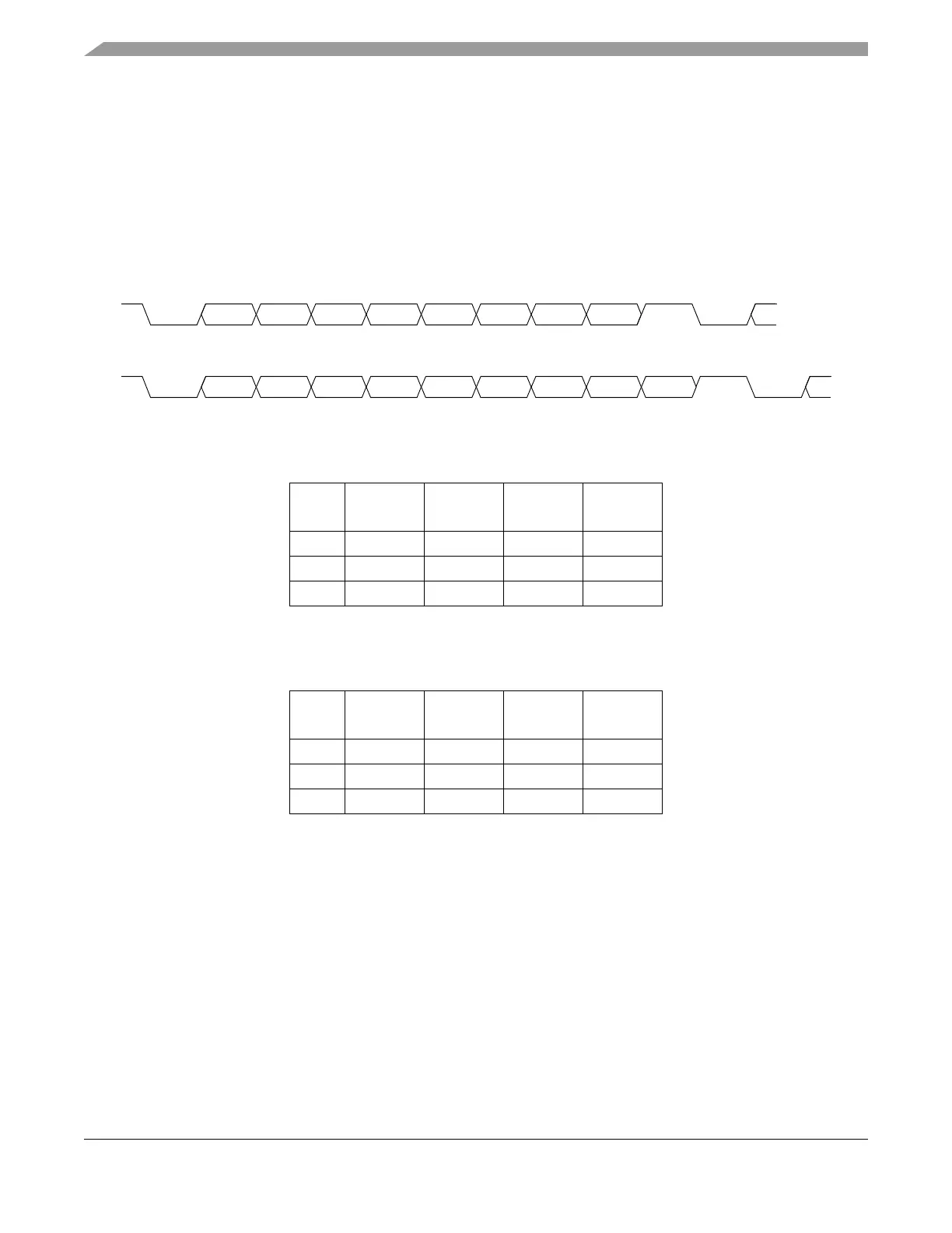
The two different data formats are illustrated in Figure 21-12. Table 21-15 and Table 21-16 show the
number of each type of bit in 8-bit data format and 9-bit data format, respectively.
Figure 21-12. eSCI Data Formats
21.4.3 Baud Rate Generation
A 13-bit modulus counter in the baud rate generator derives the baud rate for both the receiver and the
transmitter. The value, 1 to 8191, written to the SBR0–SBR12 bits determines the system clock divider.
The SBR bits are in the eSCI control register 1 (ESCIx_CR1). The baud rate clock is synchronized with
the system clock and drives the receiver. The baud rate clock divided by 16 drives the transmitter. The
receiver has an acquisition rate of 16 samples per bit time.
Baud rate generation is subject to one source of error:
• Integer division of the system clock may not give the exact target frequency.
Table 21-17 lists some examples of achieving target baud rates with a system clock frequency of 128 MHz.
Table 21-15. Example of 8-bit Data Formats
Start
Bit
Data
Bits
Address
Bits
Parity
Bits
Stop
Bit
18001
17011
17 1
1
1
The address bit identifies the frame as an address char-
acter. See Section 21.4.5.6, “Receiver Wake-up.”
01
Table 21-16. Example of 9-Bit Data Formats
Start
Bit
Data
Bits
Address
Bits
Parity
Bits
Stop
Bit
19001
18011
18 1
1
1
The address bit identifies the frame as an address char-
acter. See Section 21.4.5.6, “Receiver Wake-up.”
01
Parity or
STOP
Bit
Bit 0 Bit 1Bit 2Bit 3Bit 4Bit 5Bit 6Bit 7
Next
START
Bit
START
Bit
Data Bit
8-bit Data Format
Bit M in ESCIx_CR1 Clear
STOP
Bit
Bit 0 Bit 1Bit 2Bit 3Bit 4Bit 5Bit 6Bit 7
Next
START
Bit
START
Bit
9-bit Data Format
Bit M in ESCIx_CR1 Set
Parity or
Bit 8
Data Bit