MPC5553/MPC5554 Microcontroller Reference Manual, Rev. 5
Freescale Semiconductor 7-1
Chapter 7
Crossbar Switch (XBAR)
7.1 Introduction
This chapter describes the multi-port crossbar switch (XBAR), which supports simultaneous connections
between four (three for MPC5554) master ports and five slave ports. XBAR supports a 32-bit address bus
width and a 64-bit data bus width at all master and slave ports.
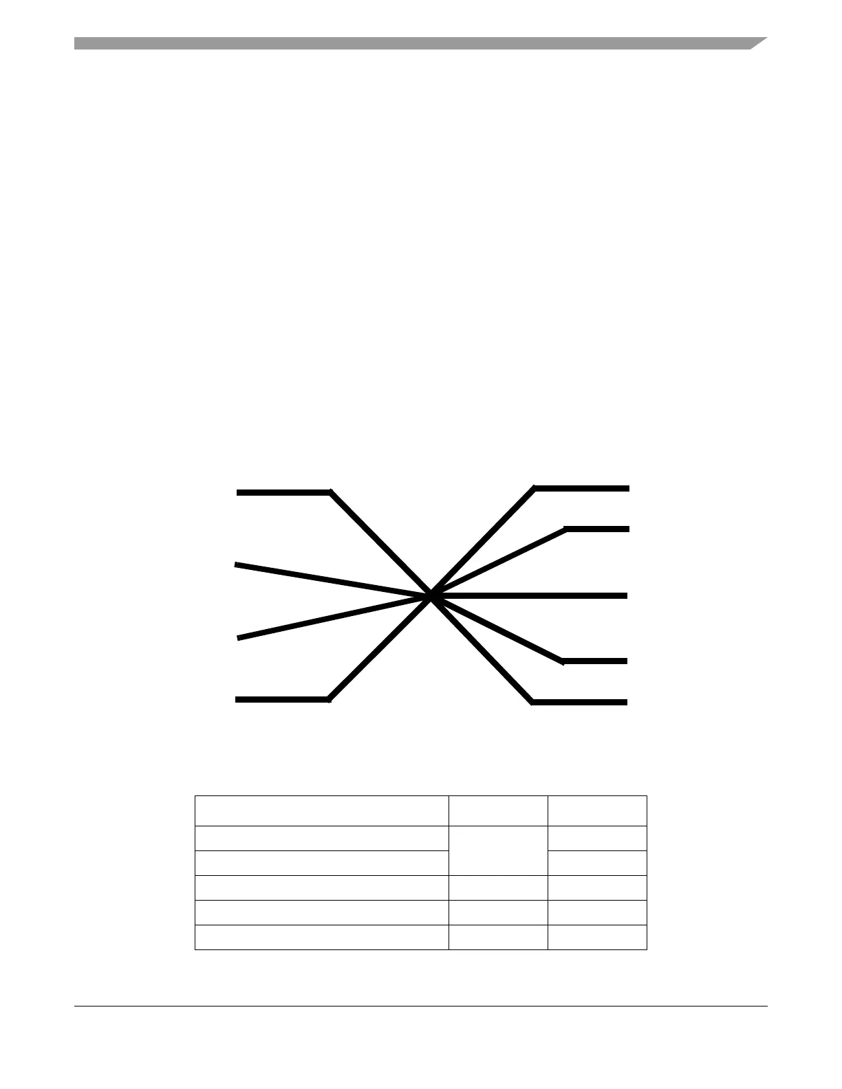
7.1.1 Block Diagram
Figure 7-1 shows a block diagram of the crossbar switch. Table 7-1 gives the crossbar switch port for each
master and slave, and the assigned and fixed ID number for each master.
Figure 7-1. XBAR Block Diagram
Table 7-1. XBAR Switch Ports
Module XBAR Port Master ID
e200z6 core—CPU instruction/data Master 0 0
e200z6—Nexus 1
eDMA Master 1 2
External Bus Interface Master 2 3
FEC (MPC5553 only) Master 3 4
e200z6 Core
eDMA
EBI
Flash
EBI
(32-bit)
Internal SRAM
Peripheral
Bridge A (32-bit)
Peripheral
Bridge B (32-bit)
(64-bit)
(32-bit)
(64-bit)
(64-bit)
(in MPC5553 only)
(64-bit)
FEC