MPC5553/MPC5554 Microcontroller Reference Manual, Rev. 5
Freescale Semiconductor 12-71
12.5.4 Connecting an MCU to Multiple Memories
The MCU can be connected to more than one memory at a time.
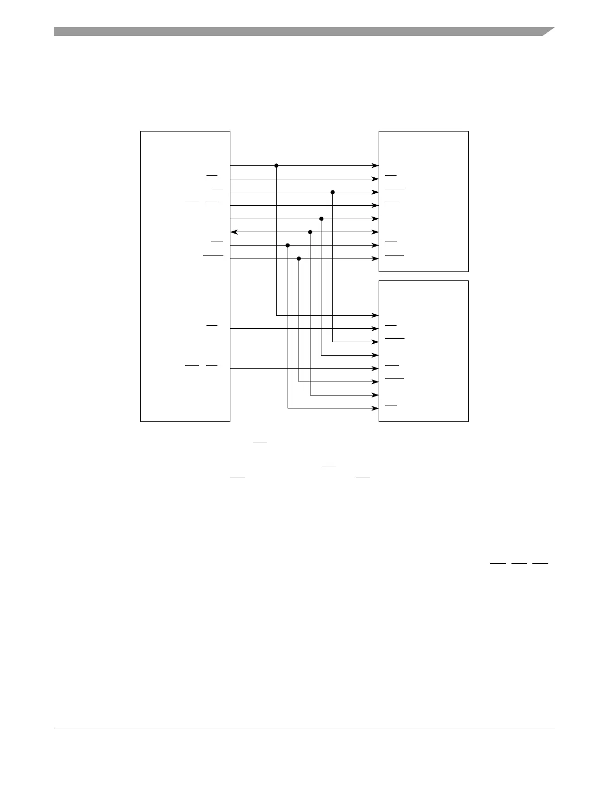
Figure 12-55 shows an example of how two memories could be connected to one MCU.
Figure 12-55. MCU Connected to Multiple Memories
12.5.5 Dual-MCU Operation with Reduced Pinout MCUs
Some MCUs with this EBI may not have all the pins described in this document pinned out for a particular
package. Some of the most common pins to be removed are DATA[16:31], arbitration pins (BB
, BG, BR),
and TSIZ[0:1]. This section describes how to configure dual-MCU systems for each of these scenarios.
More than one section may apply if the applicable pins are not present on one or both MCUs.
12.5.5.1 Connecting 16-bit MCU to 32-bit MCU (Master/Master or Master/Slave)
This scenario is straightforward. Simply connect DATA[0:15] between both MCUs, and configure both for
16-bit data bus mode operation (DBM=1 in EBI_MCR). Note that 32-bit external memories are not
supported in this scenario.
CLKOUT
CS0
TS
WE0/BE0
ADDR[8:29]
DATA[0:31]
BDIP
OE
MCU
CK
CE
ADV
WE**
A[0:21]
D[0:31]
OE
BAA*
SDR
Memory
CK
CE
ADV
WE**
A[0:21]
D[0:31]
OE
BAA*
SDR
Memory
CS
1
WE1/BE1
*May or may not be connected, depending on the memory used.
Flash memories typically use one WE signal as shown, RAMs use 2 or 4 (16-bit or 32-bit).**
Note: On a 32-bit bus, RAM memories use all four WE/BE[0:3]. On a 16-bit bus, one
RAM memory uses WE/BE[0:1] and the other uses WE/BE[2:3].