MPC5553/MPC5554 Microcontroller Reference Manual, Rev. 5
Freescale Semiconductor 15-1
Chapter 15
Internal Static RAM (SRAM)
15.1 Introduction
15.1.1 Block Diagram
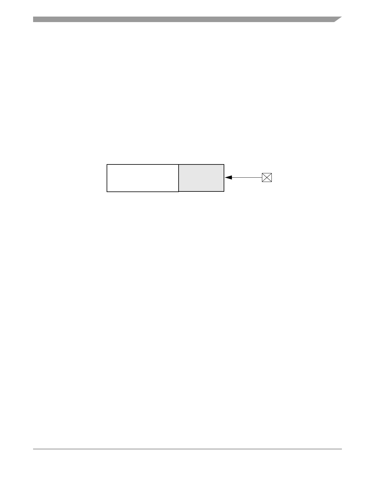
The internal SRAM block diagram is shown in Figure 15-1
Figure 15-1. Internal SRAM Block Diagram
15.1.2 Overview
The SRAM provides 64 KB of general-purpose system SRAM. The first 32 KB block of the SRAM is
powered by its own power supply pin for standby operation.
15.1.3 Features
The SRAM controller includes the following features:
• Supports read/write accesses mapped to the SRAM memory from any master
• 32 KB block powered by separate supply for standby operation
• Byte, halfword, word, and doubleword addressable
• ECC performs single-bit correction and double-bit error detection
15.2 Modes of Operation
15.2.1 Normal (Functional) Mode
Allows reads and writes of the SRAM memory arrays.
15.2.2 Standby Mode
Preserves the 32 KB of standby memory when the 1.5 V power is less than the level of V
STBY
.
SRAM
V
STBY
32-KB
Standby RAM