MPC5553/MPC5554 Microcontroller Reference Manual, Rev. 5
Freescale Semiconductor 21-25
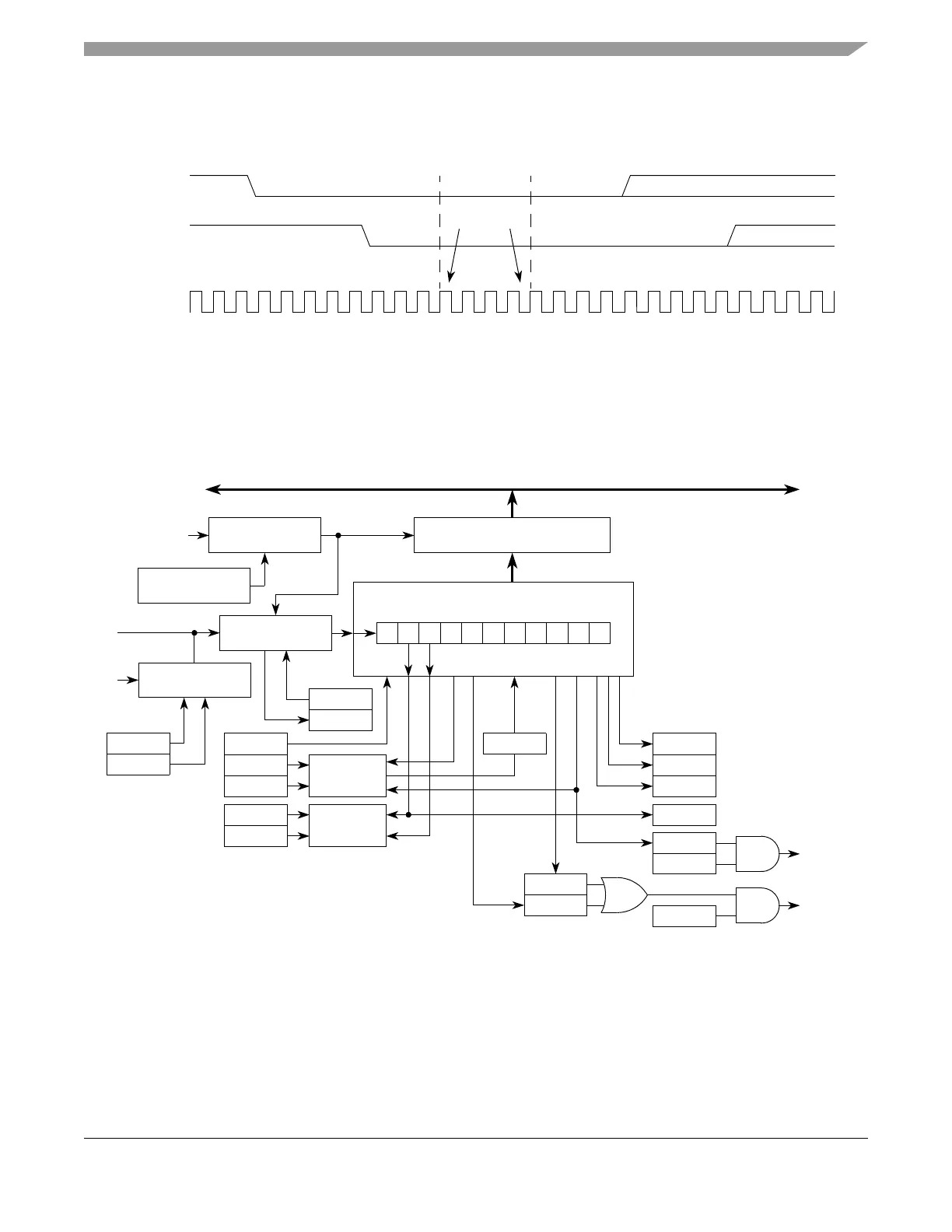
To adjust to different bus loads the sample point at which the incoming bit is compared to the one which
was transmitted can be selected with the BESM13 bit (see Figure 21-15). If set, the comparison will be
performed at RT clock 13, otherwise at RT clock 9 (also see Section 21.4.5.3, “Data Sampling.”).
Figure 21-15. Fast Bit Error Detection Timing Diagram
21.4.5 Receiver
Figure 21-16 illustrates the eSCI receiver.
Figure 21-16. eSCI Receiver Block Diagram
21.4.5.1 Receiver Character Length
The eSCI receiver can accommodate either 8-bit or 9-bit data characters. The state of the M bit in eSCI
control register 1 (ESCIx_CR1) determines the length of data characters. When receiving 9-bit data, bit
R8 in the eSCI data register (ESCIx_DR) is the ninth bit (bit 8).
Clock
BESM13 = 0 BESM13 = 1
135791113152 4 6 8 10 12 14 16
RT Clock
Count
TX Output
Shift Reg
RX Input
Shift Reg
Compare
Sample
Points
RXD
H 8 7 6 5 4 3 2 1 0 L
11-bit Receive Shift Register
STOP START
MSB
BAUD Divider
Bus
Clock
SBR0–SBR12
ILIE
IDLE
LOOP Control
IDLE
Interrupt
Request
RIE
RDRF/OR
Interrupt
Request
RSRC
LOOPS
TXD
Internal Bus
SCI Data Registers
Data Recovery
RAF
RE
WAKE
M
ILT
Wake-up
Logic
All 1s
Parity
Checking
PE
PT
NF
FE
PE
RDRF
OR
R8
RWU