MPC5553/MPC5554 Microcontroller Reference Manual, Rev. 5
Freescale Semiconductor 19-105
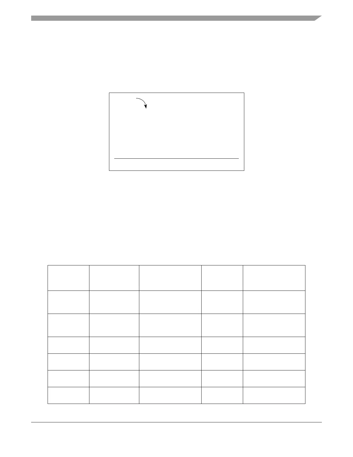
collecting all these values, they will be added according to the RSD algorithm to create the 12-bit digital
representation of the original analog input. The bits are added in the following manner:
19.4.9.2.3 RSD Adder
The array, s1 to s12,will be the digital output of the RSD ADC with s1 being the msb and s12 being the
lsb (least significant bit).
Figure 19-63. RSD Adder
19.5 Initialization/Application Information
19.5.1 Multiple Queues Control Setup Example
This section provides an example of how to configure multiple user command queues. Table 19-56
describes how each queue can be used for a different application. Also documented in this section are
general guidelines on how to initialize the on-chip ADCs and the external device, and how to configure
the command queues and the eQADC.
Table 19-56. Example Applications of Each Command Queue
Command
Queue Number
Queue Type Running Speed
Number of
Contiguous
Conversions
Example
0 Very fast burst
time-based queue
every 2 s for 200 s;
pause for 300 s and then
repeat
2 Injector current profiling
1Fast
hardware-triggered
queue
every 900 s 3 Current sensing of PWM
controlled actuators
2 Fast repetitive
time-based queue
every 2 ms 8 Throttle position
3 Software-triggered
queue
every 3.9 ms 3 Command triggered by
software strategy
4 Repetitive
angle-based queue
every 625 us 7 Airflow read every 30
degrees at 8000 RPM
5 Slow repetitive
time-based queue
every 100 ms 10 Temperature sensors
b1
a13
Carry
b12
b11
a3
a2
a12
b2
• • •
• • ••••
•••b10
a11
s1
+
s2• • ••••s10s11s12