System Interface Unit (SIU)
MPC5553/MPC5554 Microcontroller Reference Manual, Rev. 5
6-2 Freescale Semiconductor
6.1.1 Block Diagram
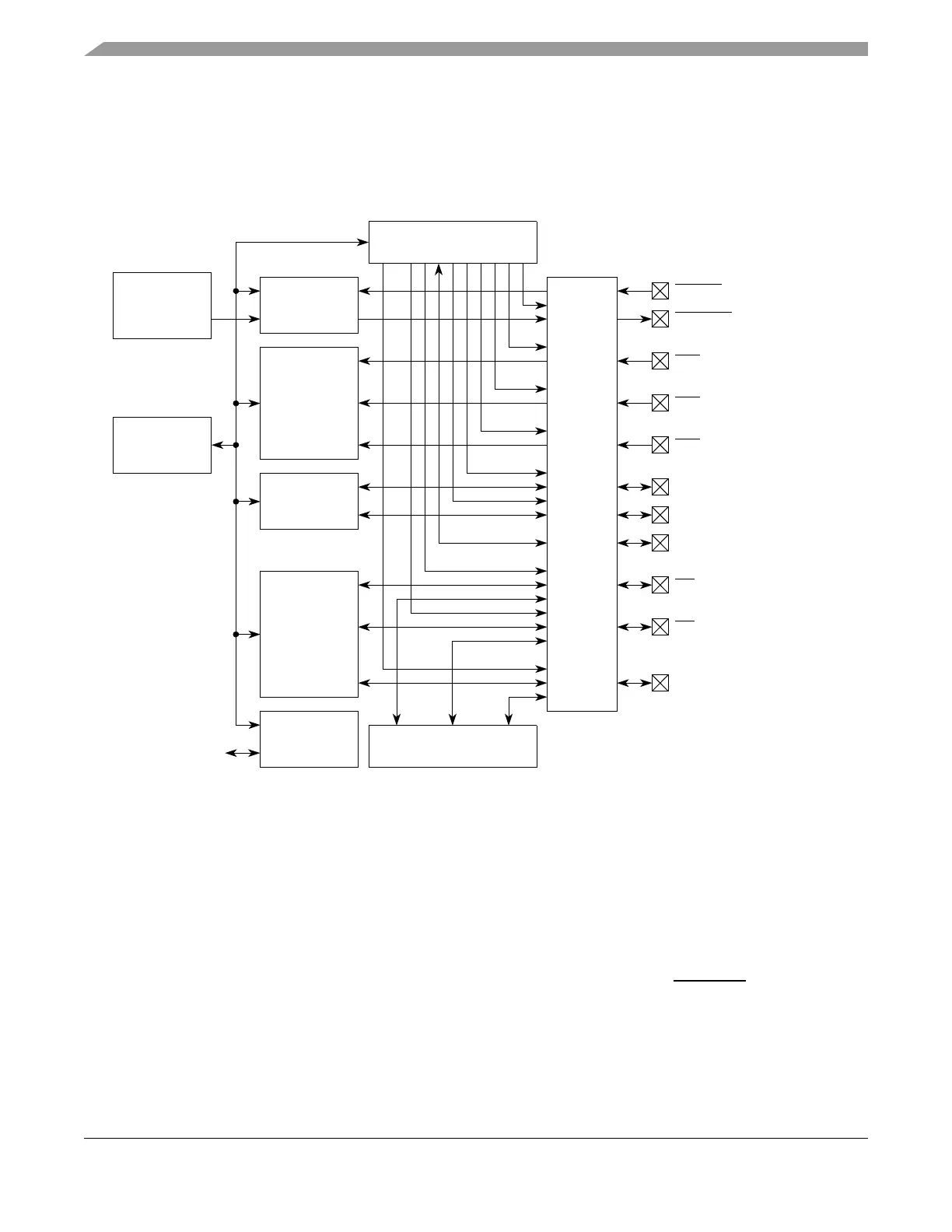
Figure 6-1 is a block diagram of the SIU. The signals shown are external pins to the device. The SIU
registers are accessed through the crossbar switch. The power-on reset detection module, pad interface/pad
ring module, and peripheral I/O channels are external to the SIU.
Figure 6-1. SIU Block Diagram
6.1.2 Overview
The MPC5553/MPC5554 system integration unit (SIU) controls MCU reset configuration, pad
configuration, external interrupt, general-purpose I/O (GPIO), internal peripheral multiplexing, and the
system reset operation. The reset configuration module contains the external pin boot configuration logic.
The pad configuration module controls the static electrical characteristics of I/O pins. The GPIO module
provides uniform and discrete input/output control of the I/O pins of the MCU. The reset controller
performs reset monitoring of internal and external reset sources, and drives the RSTOUT pin. The SIU is
accessed by the e200z6 core through the system bus crossbar switch (XBAR) and the peripheral bridge A
(PBRIDGE_A).
Reset
RESET
Configuration
SIU
Registers
Reset
Controller
Pad
Interface/
Pad
Ring
Pad Configuration
RSTOUT
Power-on
Reset
Detection
External
IRQ/
Edge
Detects
GPIO
Peripheral
I/O Channels
IMUX
IRQ Inputs,
DSPI Signals, &
eQADC Triggers
IRQ[0]
IRQ[1]
IRQ[15]
BOOTCFG[0]_GPIO[211]
WKPCFG_GPIO[213]
CS[0]_GPIO[0]
CS[1]_GPIO[1]
PLLCFG[1]_GPIO[209]
•
•
•
•
•
•
•
•
•
• • •
•
•
•
•
•
• • •
BOOTCFG[1]_GPIO[212]
•
•
•