MPC5553/MPC5554 Microcontroller Reference Manual, Rev. 5
22-6 Freescale Semiconductor
The FlexCAN2 module stores CAN messages for transmission and reception using a message buffer
structure. Each individual MB is formed by 16 bytes mapped in memory as described in Table 22-3. The
FlexCAN2 module can manage up to 64 message buffers. Table 22-3 shows a standard/extended message
buffer (MB0) memory map, using 16 bytes (0x80–0x8F) total space.
NOTE
Reading the C/S word of a message buffer (the first word of each MB) will
lock it, preventing it from receiving further messages until it is unlocked
either by reading another MB or by reading the timer.
22.3.2 Message Buffer Structure
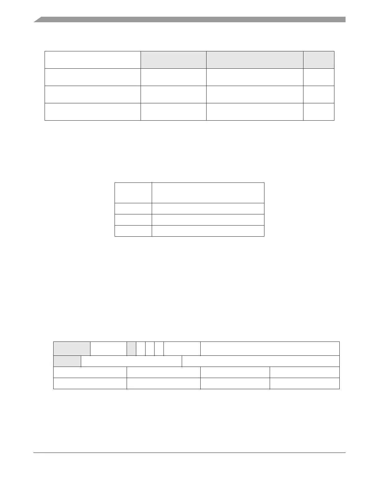
The message buffer structure used by the FlexCAN2 module is represented in Figure 22-2. Both extended
and standard frames (29-bit identifier and 11-bit identifier, respectively) used in the CAN specification
(version 2.0 Part B) are represented.
Base + 0x0060–
Base + 0x007F
— Reserved —
Base + 0x0080–
Base + 0x017F
MB0–MB15 Message buffers 0–15 128 bits
per MB
Base + 0x0180–
Base + 0x027F
MB16–MB31 Message buffers 16–31 128 bits
per MB
Base + 0x0280–
Base + 0x047F
MB32–MB63 Message buffers 32–63 128 bits
per MB
1
The MPC5554 has FlexCAN2 modules A, B, and C, whereas the MPC5553 only has FlexCAN2 modules A and C.
Table 22-3. Message Buffer MB0 Memory Mapping
Address
Offset
MB Field
0x80 Control and Status (C/S)
0x84 Identifier Field
0x88–0x8F Data fields 0–7 (1 byte each)
012345678910111213141516171819202122232425262728293031
0x0
CODE
SRR
IDE
RTR
LENGTH TIME STAMP
0x4
ID (Extended/Standard) ID (Extended)
0x8 Data Byte 0 Data Byte 1 Data Byte 2 Data Byte 3
0xC Data Byte 4 Data Byte 5 Data Byte 6 Data Byte 7
Figure 22-2. Message Buffer Structure
Table 22-2. Module Memory Map (Continued)