MPC5553/MPC5554 Microcontroller Reference Manual, Rev. 5
13-6 Freescale Semiconductor
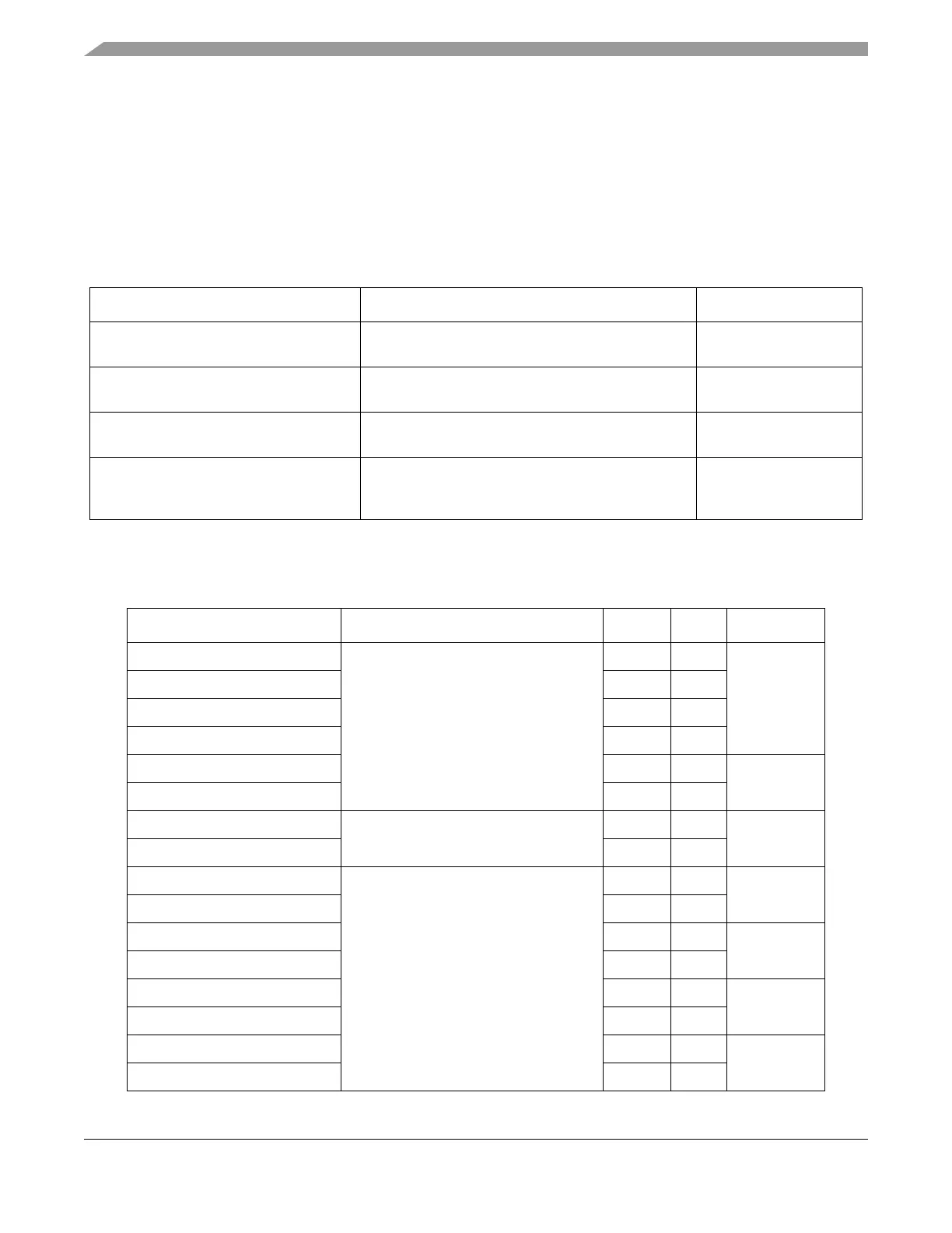
13.3.1 Flash Memory Map
Table 13-3 shows the flash array memory map and how it is mapped assuming byte addressing.
Base addresses for the MPC5554 and the MPC5553 are the following:
• Shadow base address = 0x00FF_FC00
• Array base address = 0x0000_0000
• Control registers base address = 0xC3F8_8000
Table 13-4 shows how the array is partitioned into three address spaces — low, mid, and high — and into
partitions and blocks.
Table 13-3. Module Flash Array Memory Map
Byte Address Use Access
Shadow base + 0x00_0000–
Shadow base + 0x00_03FF
Shadow block space (1024 Bytes) User
Array Base + 0x00_0000–
Array Base + 0x03_FFFF
Low- address space (256 KB) User
Array Base + 0x04_0000–
Array Base + 0x07_FFFF
Mid-address space (256 KB) User
Array Base + 0x08_0000 to
Array Base + 0x1F_FFFF (MPC5554) or to
Array Base + 0x17_FFFF (MPC5553)
High-address space (1.5 MB in MPC5554 or 1.0 MB
in MPC5553)
User
Table 13-4. Flash Partitions
Address Use Block Size Partition
Array Base + 0x00_0000 Low-address space L0 16K 1
Array Base + 0x00_4000 L1 48K
Array Base + 0x01_0000 L2 48K
Array Base + 0x01_C000 L3 16K
Array Base + 0x02_0000 L4 64K 2
Array Base + 0x03_0000 L5 64K
Array Base + 0x04_0000 Mid-address space M0 128K 3
Array Base + 0x06_0000 M1 128K
Array Base + 0x08_0000 High-address space
(MPC5554 and MPC5553)
H0 128K 4
Array Base + 0x0A_0000 H1 128K
Array Base + 0x0C_0000 H2 128K 5
Array Base + 0x0E_0000 H3 128K
Array Base + 0x10_0000 H4 128K 6
Array Base + 0x12_0000 H5 128K
Array Base + 0x14_0000 H6 128K 7
Array Base + 0x16_0000 H7 128K