MPC5553/MPC5554 Microcontroller Reference Manual, Rev. 5
20-52 Freescale Semiconductor
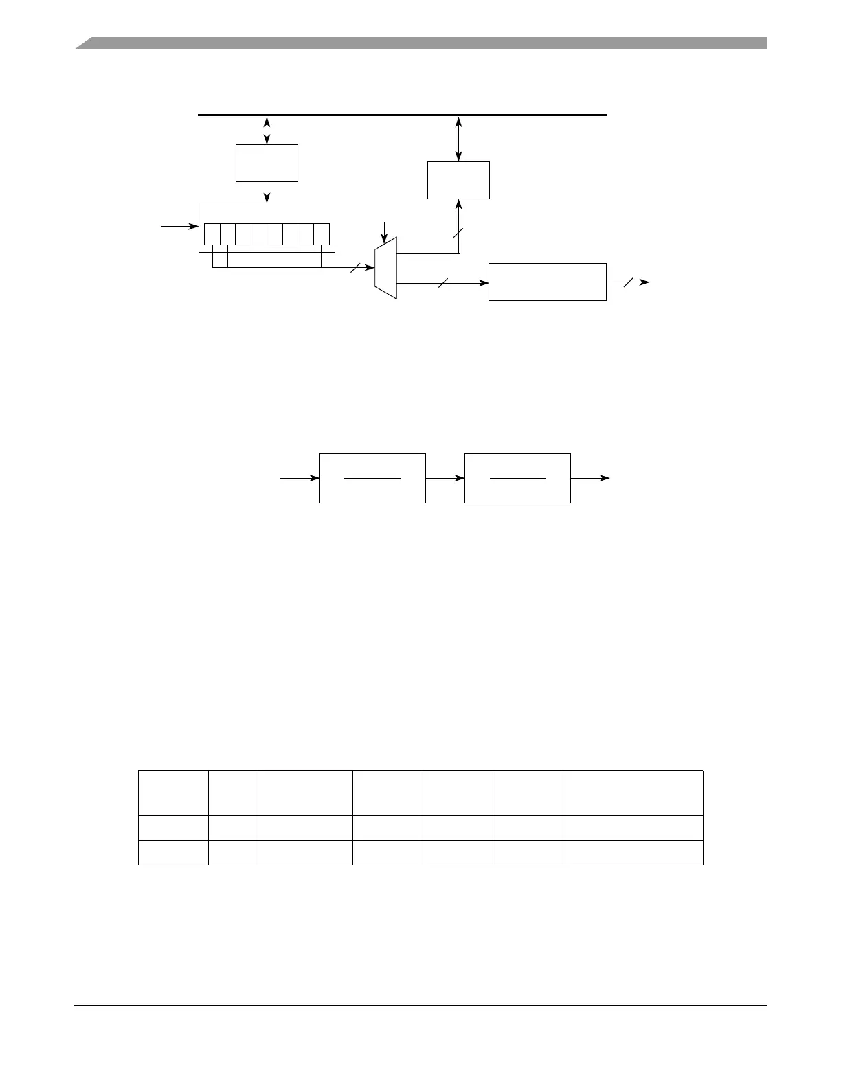
Figure 20-33. CSI Deserialization Diagram
20.4.6 DSPI Baud Rate and Clock Delay Generation
The SCK frequency and the delay values for serial transfer are generated by dividing the system clock
frequency by a prescaler and a scaler with the option of doubling the baud rate. Figure 20-34 shows
conceptually how the SCK signal is generated.
Figure 20-34. Communications Clock Prescalers and Scalers
20.4.6.1 Baud Rate Generator
The baud rate is the frequency of the serial communication clock (SCK). The system clock is divided by
a baud rate prescaler (defined by DSPIx_CTAR[PBR]) and baud rate scaler (defined by
DSPIx_CTAR[BR]) to produce SCK with the possibility of doubling the baud rate. The DBR, PBR, and
BR fields in the DSPIx_CTARs select the frequency of SCK using the following formula:
Table 20-23 shows an example of a computed baud rate.
20.4.6.2 PCS to SCK Delay (t
CSC
)
The PCS to SCK delay is the length of time from assertion of the PCS signal to the first SCK edge. See
Figure 20-36 for an illustration of the PCS to SCK delay. The PCSSCK and CSSCK fields in the
Table 20-23. Baud Rate Computation Example
f
SYS PBR
Prescaler
Value
BR
Scaler
Value
DBR
Value
Baud Rate
100 MHz 0b00 2 0b0000 2 0 25 Mb/s
20 MHz 0b00 2 0b0000 2 1 10 Mb/s
SIN
Control
Logic
0 1 • • • • • 15
Shift Register
16
Slave Bus Interface
Parallel
DSI Deserialization
Data Register
Outputs
16
Tra ns fe r
Priority Logic
16
RX FIFO
(P_OUT)
16
Prescaler
1
Scaler
1+DBR
System Clock SCK
SCK baud rate
f
SYS
PBRPrescalerValue
----------------------------------------------------------
1DBR+
BRScalerValue
--------------------------------------------
=