MPC5553/MPC5554 Microcontroller Reference Manual, Rev. 5
20-40 Freescale Semiconductor
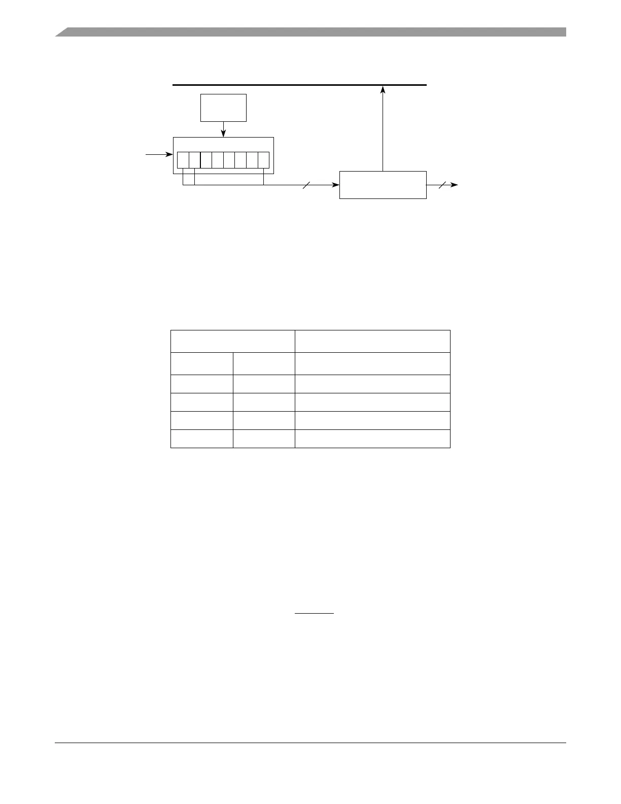
Figure 20-20. DSI Deserialization Diagram
20.4.4.5 DSI Transfer Initiation Control
Data transfers for a master DSPI in DSI configuration are initiated by a condition. When chaining DSPIs,
the master and all slaves must be configured for the transfer initiation. The transfer initiation conditions
are selected by the TRRE and CID bits in the DSPIx_DSICR. Table 20-18 lists the four transfer initiation
conditions.
20.4.4.5.1 Continuous Control
For continuous control, the initiation of a transfer is based on the baud rate at which data is transferred
between the DSPI and the external device. The baud rate is set in the DSPIx_CTAR selected by the
DSICTAS field in the DSPIx_DSICR. A new DSI frame shifts out when the previous transfer cycle has
completed and the delay after transfer (t
DT
) has elapsed.
20.4.4.5.2 Change In Data Control
For change in data control, a transfer is initiated when the data to be serialized has changed since the
transfer of the last DSI frame. A copy of the previously transferred DSI data is stored in the
DSPIx_COMPR. When the data in the DSPIx_SDR or the DSPIx_ASDR is different from the data in the
DSPIx_COMPR, a new DSI frame is transmitted. The TXSS bit in the DSPIx_DSICR selects which
register the DSPIx_COMPR is compared to. The MTRIG output signal is asserted every time a change in
data is detected.
20.4.4.5.3 Triggered Control
For triggered control, initiation of a transfer is controlled by the internal hardware trigger signal (ht). The
TPOL bit in the DSPIx_DSICR selects the active edge of ht. For ht to have any affect, the TRRE bit in the
DSPIx_DSICR must be set.
Table 20-18. DSI Data Transfer Initiation Control
DSPIx_DSICR Bits
TRRE CID Type of Transfer Initiation Control
0 0 Continuous
0 1 Change in Data
1 0 Triggered
1 1 Triggered or Change in Data
SIN
Control
Logic
0 1 • • • • • 15
Shift Register
16
Slave Bus Interface
ParallelDSI Deserialization
Data Register
Outputs
16