MPC5553/MPC5554 Microcontroller Reference Manual, Rev. 5
Freescale Semiconductor 20-39
If the CID bit in the DSPIx_DSICR is set and the data in the DSPIx_COMPR differs from the selected
source of the serialized data, the slave DSPI will assert the MTRIG signal. If the slave’s internal hardware
trigger signal is asserted and the TRRE is set, the slave DSPI asserts MTRIG. These features are included
to support chaining of several DSPI. Details about the MTRIG signal are found in Section 20.4.4.7,
“Multiple Transfer Operation (MTO).”
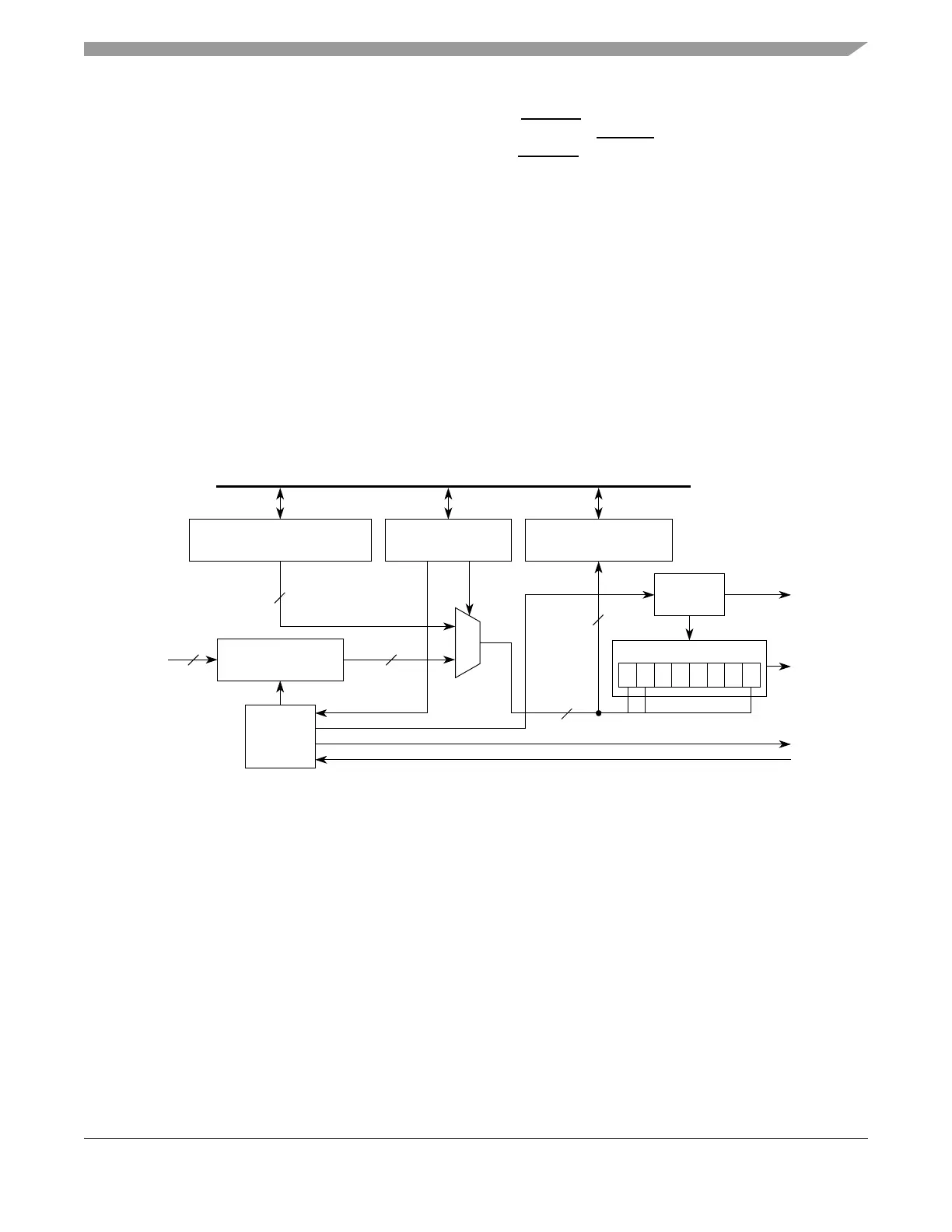
20.4.4.3 DSI Serialization
In the DSI configuration, 4 to 16 bits can be serialized using two different sources. The TXSS bit in the
DSPIx_DSICR selects between the DSPIx_SDR and DSPIx_ASDR as the source of serialized data. See
Section 20.3.2.11, “DSPI DSI Serialization Data Register (DSPIx_SDR),” and Section 20.3.2.12, “DSPI
DSI Alternate Serialization Data Register (DSPIx_ASDR),” for more details. The DSPIx_SDR holds the
latest parallel input signal values which is sampled at every rising edge of the system clock. The
DSPIx_ASDR is written by host software and used as an alternate source of serialized data.
A copy of the last DSI frame shifted out of the shift register is stored in the DSPIx_COMPR. This register
provides added visibility for debugging and it serves as a reference for transfer initiation control.
Figure 20-19 shows the DSI serialization logic. Section 20.3.2.13, “DSPI DSI Transmit Comparison
Register (DSPIx_COMPR),” contains details on the DSPIx_COMPR.
Figure 20-19. DSI Serialization Diagram
20.4.4.4 DSI Deserialization
When all bits in a DSI frame have been shifted in, the frame is copied to the DSPIx_DDR. This register
presents the deserialized data as parallel output signal values. The DSPIx_DDR is memory mapped to
allow host software to read the deserialized data directly. Figure 20-20 shows the DSI deserialization logic.
for more information on the DSPIx_DDR, refer to Section 20.3.2.14, “DSPI DSI Deserialization Data
Register (DSPIx_DDR).”
1
0
DSPI Alternate
Serialization Data Register
SOUT
Parallel
DSI Configuration
Register
DSI Transmit
Comparison Register
Clock
Logic
0 1 • • • • • 15
Shift Register
DSI Serialization
Data Register
Control
Logic
SCK
Inputs
PCS
ht
16
16
16
16
TXSS
Slave Bus Interface
16