MPC5553/MPC5554 Microcontroller Reference Manual, Rev. 5
2-12 Freescale Semiconductor
AN[15]_
32
FCK
33
Single-ended Analog Input
eQADC Free Running Clock
MP
G
I
O
V
DDEH9
34
A, M I / – AN[15] / – C16 A15 D16 C13
AN[16:18] Single-ended Analog Inputs P I V
DDA1
31
AE I / –
AN[16:18] /
–
B7, E8,
H12
A6, C5,
D8
B7, C6,
D9
C6, C4,
D5
AN[19:20] Single-ended Analog Inputs P
I
V
DDA1
31
AE I / –
AN[19:20] /
–
C7:8 B5:6 B6, C7 —
AN[21] Single-ended Analog Input P
I
V
DDA1
31
AE I / – AN21 / – E9 C7 C8 B4
AN[22:25] Single-ended Analog Inputs P
I
V
DDA0
31
AE I / –
AN[22:25] /
–
C11,
B11,
H13,
E12
B10,
A10,
D11,
C11
C11,
B11,
D12, C12
B8,
C9,
D8, B9
AN[26] Single-ended Analog Input P
I
V
DDA0
31
AE I / – AN[26] / – C12 B11 B12 —
AN[27:28] Single-ended Analog Input P
I
V
DDA0
31
AE I / –
AN[27:28] /
–
B12,
A13
A11:12 A12:13
A10,
B10
AN[29] Single-ended Analog Input P
I
V
DDA0
31
AE I / – AN[29] / – E13 D12 D13 —
AN[30:35] Single-ended Analog Inputs P
I
V
DDA0
31
AE I / –
AN[30:35] /
–
C13,
B13:14,
E14,
G14,
A14
C12,
B12:13,
C13,
D13,
A13
C13,
B13:14,
C14,
D14, A14
D9:10,
C10:11,
C5, D11
AN[36:39] Single-ended Analog Inputs P I V
DDA1
31
AE I / –
AN[36:39] /
–
C5, B5,
B4. C6
B3, A3,
D5, B4
B4, A4,
D6, B5
F4, E3,
B3, D2
ETRIG[0:1]_
GPIO[111:112]
eQADC Trigger Inputs
General Purpose I/Os
P
G
I
I/O
V
DDEH8
S – / Up – / Up
A16
,
B16
B16
,
A16
——
V
RH
Voltage Reference High P I
V
DDA0
31
V
DDINT
– / – V
RH
A9 A9 A10 A8
V
RL
Voltage Reference Low P I
V
DDA0
31
V
SSINT
– / – V
RL
A10 C10 A11 A9
REFBYPC
Reference Bypass Capacitor
Input
PI
V
DDA0
31
AE – / – REFBYPC B10 B9 B10 B7
eTPU Signals
TCRCLKA_
IRQ
[7]_
GPIO[113]
eTPU A TCR Clock
External Interrupt Request
General Purpose I/O
P
A
G
I
I
I/O
V
DDEH1
S – / Up – / Up N5 N4 M2 L4
ETPUA[0:3]_
ETPUA[12:15]_
GPIO[114:117]
eTPU A Channel
eTPU A Channel (output only)
General Purpose I/O
P
A
G
I/O
O
I/O
V
DDEH1
S
– /
WKPCFG
– /
WKPCFG
M5, G8,
M3, L3
N3,
M4, M3,
M2
L3:4,
K3, L2
N3, M3,
P2, P1
ETPUA[4:7]_
ETPUA[16:19]_
GPIO[118:121]
eTPU A Channel
eTPU A Channel (output only)
General Purpose I/O
P
A
G
I/O
O
I/O
V
DDEH1
S
– /
WKPCFG
– /
WKPCFG
L2, H9,
M2, K3
M1
, L4,
L3, L2
L1
, K4,
J3, K2,
N2, M4,
L3, K3
ETPUA[8:11]_
ETPUA[20:23]_
GPIO[122:125]
eTPU A Channel
eTPU A Channel (output only)
General Purpose I/O
P
A
G
I/O
O
I/O
V
DDEH1
S
– /
WKPCFG
– /
WKPCFG
K2
, G9,
L5, J3
L1
, K4,
K3, K2
K1, J4,
H3, J2
N1
, M2,
M1, L2
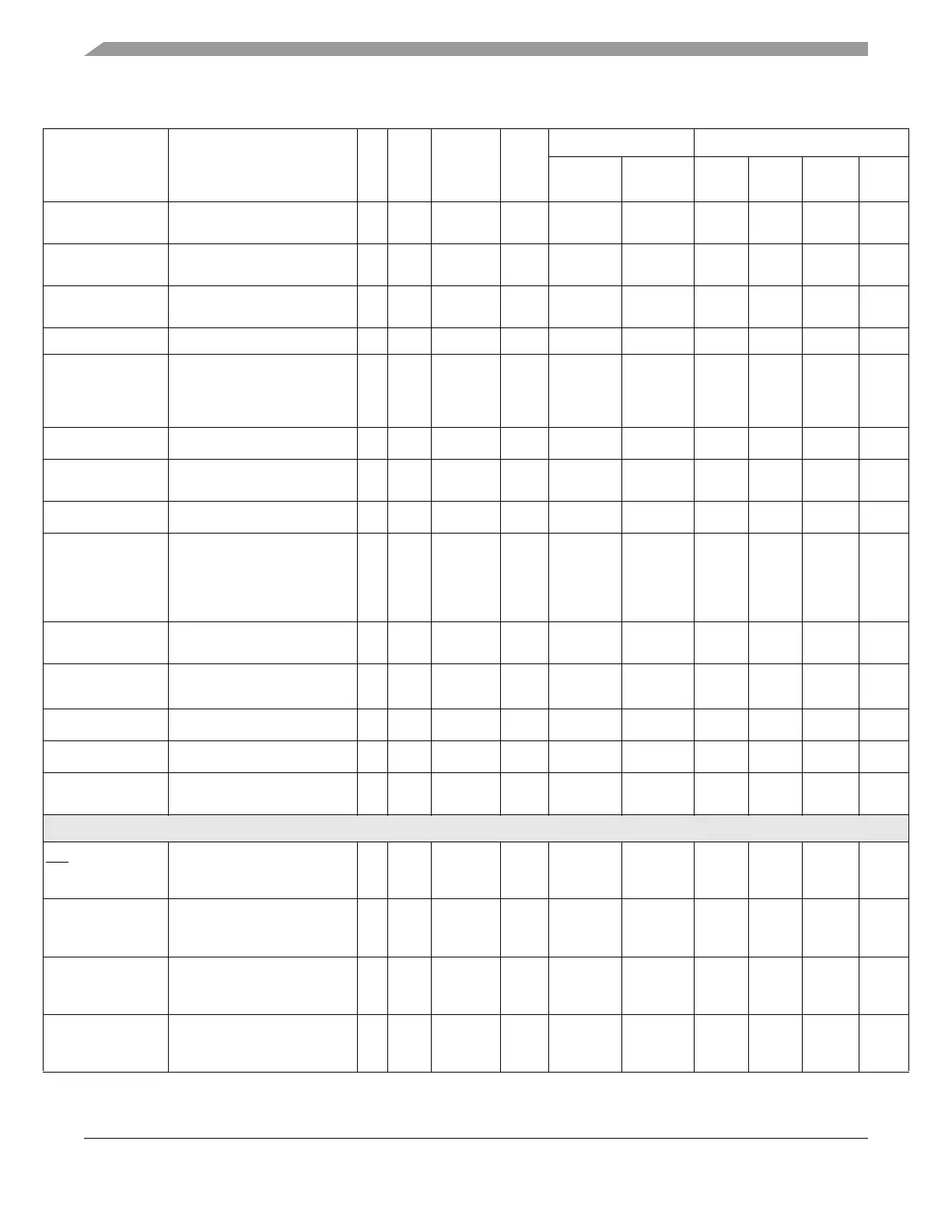
Table 2-1. MPC5553 Signal Properties (Continued)
Signal Name
1
Signal Functions
2
P/
A/G
I/O
Type
Voltage
3
Pad
Type
4
Status Pin Labels / Package Type
During
Reset
5
After
Reset
6
496
7
416
8
324 208
9