17.4.3 I/O diagnoscs
This secon describes the diagnoscs of the analog and digital inputs and outputs that can be
found on the control terminal X3.
17.4.3.1 Digital inputs and outputs
The following parameters serve to diagnose the digital inputs and outputs of the inverter.
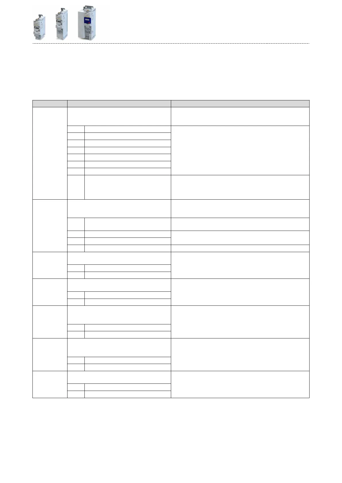
Parameter
Address Name / seng range / [default seng] Info
0x60FD
(P118.00)
Digital inputs
(Digital inputs)
•
Read only
Bit coded display of the current state of the digital inputs
Bit 16 Level from digital input 1 0 ≡ LOW level, 1 ≡ HIGH level.
Digital input 6 and digital input 7 are only available with applicaon I/O.
Bit 17 Level from digital input 2
Bit 18 Level from digital input 3
Bit 19 Level from digital input 4
Bit 20 Level from digital input 5
Bit 21 Level from digital input 6
Bit 22 Level from digital input 7
Bit 25 Internal interconnecon of digital inputs 0 ≡ digital input terminals are set to HIGH (PNP) level via pull-up resis-
tors.
1 ≡ digital input terminals are set to LOW (PNP) level via pull-up resis-
tors.
0x2DAD
(P120.00)
Internal hardware states
(Int. HW states)
•
Read only
Bit-coded display of internal hardware states.
Bit 0 Relay 0 ≡ X9/NO-COM open and NC-COM closed.
1 ≡ X9/NO-COM closed and NC-COM open.
Bit 1 Digital output 1 0 ≡ LOW level, 1 ≡ HIGH level.
Bit 2 Digital output 2
Bit 10 Charge Relay 1 ≡ precharging of the DC bus via charge relay is acve.
0x4016:005 Digital output 1: Terminal state
•
Read only
Display of the logic state of output terminal X3/DO1.
0 FALSE
1 TRUE
0x4016:006 Digital output 1: Trigger signal state
•
Read only
Display of the logic state of the trigger signal for digital output 1 (without
taking a ON/OFF delay set and inversion into consideraon).
0 FALSE
1 TRUE
0x4017:005 Digital output 2: Terminal state
•
Read only
•
Only available for applicaon I/O.
Display of the logic state of output terminal X3/DO2.
0 FALSE
1 TRUE
0x4017:006 Digital output 2: Trigger signal state
•
Read only
•
Only available for applicaon I/O.
Display of the logic state of the trigger signal for digital output 2 (without
taking a ON/OFF delay set and inversion into consideraon).
0 FALSE
1 TRUE
0x4018:005 Relay: Relay state
•
Read only
Display of the logic state of the relay.
0 FALSE
1 TRUE
Diagnoscs and fault eliminaon
Diagnosc parameters
I/O diagnoscs
605

 Loading...


