12.9.6 Diagnoscs
12.9.6.1 LED status display
Informaon about the CAN bus status can be obtained quickly via the "CAN-RUN" and "CAN-
ERR" LED displays on the front of the inverter.
The meaning can be seen from the tables below.
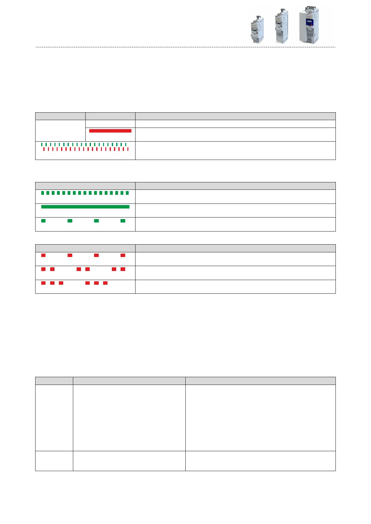
Inverter not acve on the CAN bus (yet)
LED "CAN-RUN" LED "CAN-ERR" Meaning
o
o Inverter is not acve on the CAN bus.
on
"Bus O" state.
Both LEDs are ickering alternately
Automac baud rate detecon acve.
Inverter acve on the CAN bus
The green "CAN-RUN" LED indicates the CANopen state:
LED "CAN-RUN" CANopen state
blinking fast (5 Hz)
Pre-Operaonal
on
Operaonal
blinking 1x, then goes o for 1 s
Stopped
The red "CAN-ERR" LED indicates a CANopen error:
LED "CAN-ERR" CANopen error
blinking 1x, then goes o for 1 s
Warning Limit reached
blinking 2x, then goes o for 1 s
Heartbeat Event
blinking 3x, then goes o for 1 s
Sync message error (only possible in the "Operaonal" state)
12.9.6.2 Informaon on the network
The inverter has various diagnosc parameters for displaying ...
•
the acve node address, baud rate and current DIP switch sengs;
•
the network status, the CAN master status and the status of various me monitors;
•
telegram counters.
The telegram counters are free-running, i. e. aer reaching the maximum value , the respec-
ve counter starts again at 0.
The following parameters show informaon on the network.
Parameter
Address Name / seng range / [default seng] Info
0x1001 Error register
•
Read only
Bit-coded error status.
•
Bit 0 is set if an error is acve.
The other bits signalise which group the acve error belongs to:
•
Bit 1: Current error
•
Bit 2: Voltage error
•
Bit 3: Temperature error
•
Bit 4: Communicaon error
•
Bit 5: Device prole-specic error
•
Bit 6: Reserved (always 0)
•
Bit 7: Manufacturer-specic error
0x2302:001
(P511.01)
Acve CANopen sengs: Acve node ID
(CANopen diag.: Acve node ID)
•
Read only
Display of the acve node address.
Conguring the network
CANopen
Diagnoscs
364

 Loading...


