Installation and Commissioning
GARD 8000 SYS RFL Electronics
November 28, 2017 4-46 973.334.3100
4.6.3.1.2 OUTPUT POWER
The GARD 8000 PLC transmitter is specified to provide 10W into a 50 ohm load. Adjustments to the
output power are made with a 50 ohm dummy load connected. Any additional devices in the transmit
path, such as hybrids, will reduce the effective output power. This adjustment should be performed at
the rated 10W level.
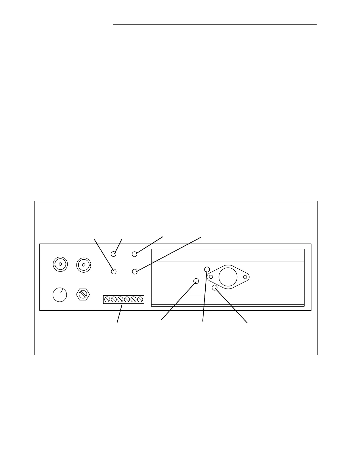
1. Connect the dummy load to the TX port. The TX port location is shown below.
2. Connect the FSVM across the output of the Power Amplifier test points (Red is the Power Amp
Output, and Black is Common). The test point locations are shown below. Set the FSVM to the
transmitter output frequency.
3. Set the transmitter to output the full 10W level. In a 1W/10W FSK or On-Off system use either
the external trip/block input or the test pages.
4. Adjust the Power Amplifiers Gain control (R8 in Figure 4-9) to achieve 22.36 Vrms
(40 dBm).
5. Disconnect the dummy load and restore the line connection.
RX
TX
COARSE FINE
GND
CLI
GND
-15
+15
TB1
Common
Test Point
(Black)
Receive In
Test Point
(Yellow)
Common
Test Point
(Black)
Power Amp Out
Test Point
(Red)
R19
Amp TX Fail
Adjust
R13
Amp Impedance
Adjust
R8
Amp Gain
Adjust
Figure 4-16. PLC Analog Module Test Points