Power Line Carrier
GARD 8000 SYS RFL Electronics
April 23, 2015 10-35 973.334.3100
10.8.13.1 SETTING JUMPERS AND SWITCHES ON THE 50W POWER
AMPLIFIER CIRCUIT BOARD
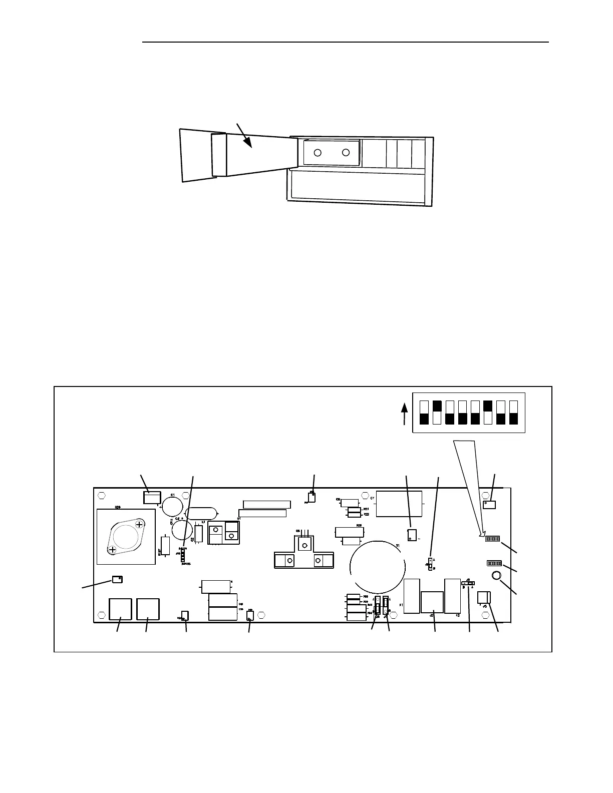
Location of 50W
Power Amp Module
Figure 10-25. Location of 50W Power Amplifier Module
The 50W Power Amplifier has a circuit board which contains two programmable jumpers, J6 and J7.
In addition to this, the board has five connectors (J1, J2, J3, J4, J5), and five potentiometers (R8, R14,
R69, R74, R83) that must be set for proper system operation. These components can be seen in below
Table 10-13 describes the functions of these components and indicates how the jumpers and
potentiometers must be set.
Effective October 2010, two DIP Switch banks SW1 and SW2 have been added to the Power Amp
Circuit Board. These switches are factory set for optimum operation but can be changed in the field if
required. See Table 10-14 for a description of the switch functions and their settings.
99347 99347
10K
4793
2SC
100UH 2A
100UF
45142-3
.1UF
2SA
1837
100UF
1837
2SA
105186
1 OHM 3W
1 OHM 3W
102757
4793
2SC
1 OHM
1 OHM
MJE182
1K
10 OHM 2W
.0068UF
1 OHM 1W
1 OHM 1W
.33UF
105186
99347
20K
10UF 100V
45142-2
2K
1/2W
2K
.22UF
.22UF
.22UF
4.7K 3W
J1
R163
J10
J4 J5 R83 R69 J6 J7
R14
R8
J2
R74
J8
J9
J3
DS1
SW1
SW2
Top View
Switch Block Typical
ON
1 2 3 4
SW2
5 6 7 8
Figure 10-26. Circuit Board, 50W Power Amp showing locations of jumpers, switches, connectors, potentiometers
As shown above; effective October 2010, two switch blocks have been added to the Power Amplifier
Circuit Board. These DIP switches are factory set to protect the circuit board from overvoltage or
excessive phase angle situations. See Table 10-14 for a description of the switch settings.