GARD DNP Configuration and SNMP Trap Agent
GARD 8000 SYS RFL Electronics
April 23, 2015 16-1 973.334.3100
SECTION 16. GARD DNP3 CONFIGURATION
AND SNMP TRAP AGENT
16.1 OVERVIEW OF GARD DNP3
The GARD controller board has factory installed software that allows the user to take advantage of the
robust and flexible features of the DNP communications protocol. Once configured, the GARD will
communicate with up to two remote DNP master computers. The remote master computers will poll
the GARD for data.
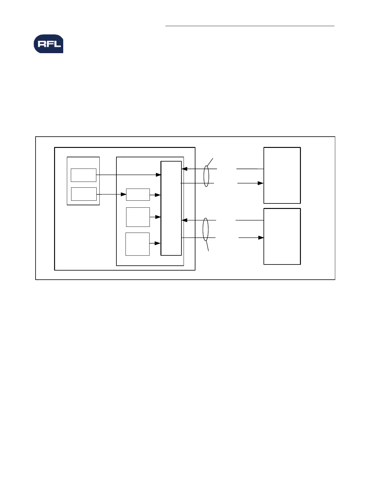
DNP Master
Computer 1
GARD 8000
Slave
Controller Board
DNP
Request
TCP/IP or
RS-485
TCP/IP
Response
Request
Response
PLC Module
Counters
Counters 1-6
Analog
Values
Scale and
Offset
GARD
Logic
GARD
System
Counters
HMI
DNP Master
Computer 2
gFigure 16-1. DNP3 Functional Block Diagram
The GARD is capable of sending the following list of data to the master computers.
o HMIOUT 0-63 (These bits can be used to indicate logical states in the GARD)*
o Analog values from any DNP supported module
o Counter values from the PLC module
o Counter values from the GARD system
* The GARD is capable of receiving HMIIN 1 to 63
See Page 16-15 for a complete list of DNP supported modules.
In order to make use of the DNP feature the user must configure the GARD appropriately using the
“DNP Configuration” web page. Once the DNP configuration page is set other parameters such as the
“scale, offset, alias” and the “Point list setting” web pages can be configured.
Unsolicited messages may be sent to either of the DNP3 master computers. Unsolicited messages are
sent when a binary object changes state or an analog value changes by more than a user adjustable