Power Line Carrier
GARD 8000 SYS RFL Electronics
April 23, 2015 10-45 973.334.3100
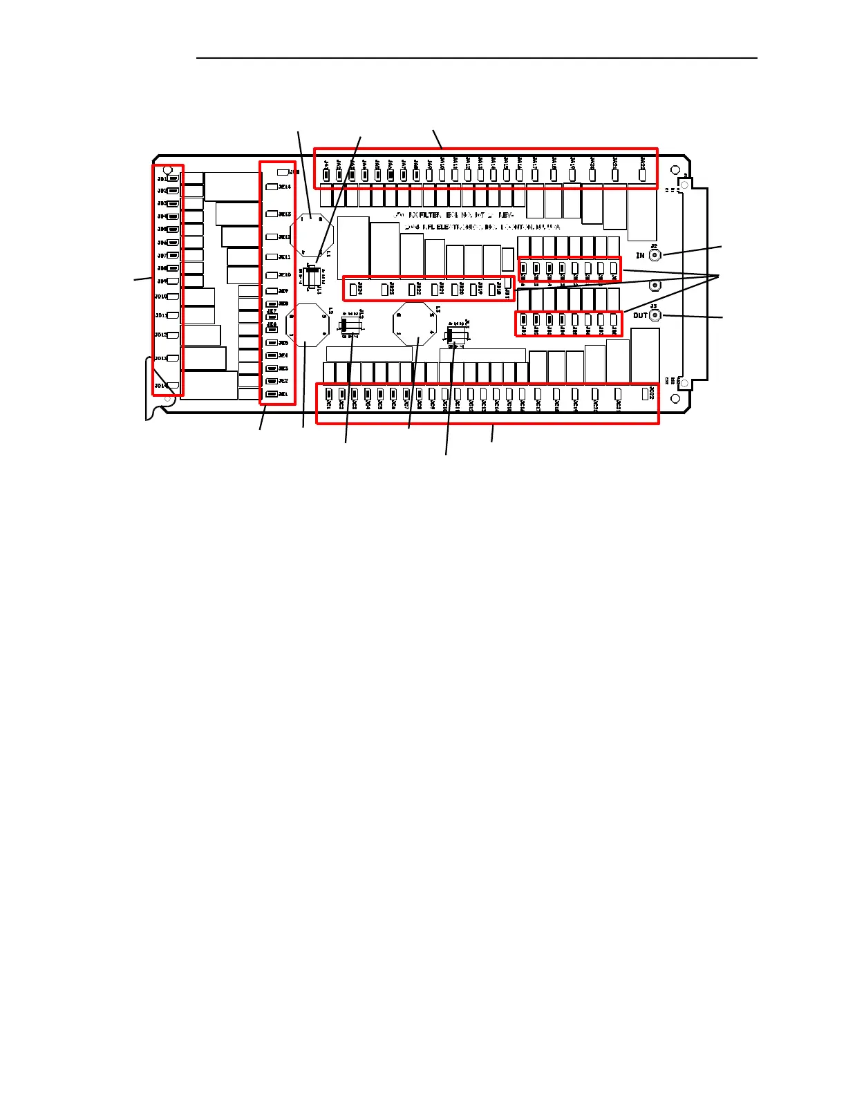
"JB"
Group
(107821
)
COIL
COIL
(107821
)
COIL
(107821
)
D
"JA" Group
"JC" Group
"JD"
Group
"JE" Group
L1
L2 L3
"JL2" Group
"JL1" Group
"JL3" Group
J2
J4
J3
Figure 10-32. Location of Jumpers on the RX Filter Board, showing Jumper groupings
10.8.13.6.1 Quick Tuning Procedure and Jumper Setting Overview
1. For the selected center frequency, set the jumpers as described in the Microsoft Excel®
Worksheet “9508 Rx Filter Programming Sheet.xls,” available on request from RFL.
2. Connect a signal generator (HP3336B or HP3325A or equivalent) to J2 of the Rx Filter.
Connect a selective level meter (Wandel & Golterman SPM-32A or 33A, Rycom 6021A,
Signalcrafters 110, or equivalent) with a terminating impedance of 50 Ohms, to J3 of the Rx
Filter. Use J4 as the ground connection.
3. Set the center frequency of the test equipment (signal generator and selective level meter)
according to the selection made in Step 1.
4 Adjust inductors L1, L2 and L3 to have a minimum loss (highest voltage level) at the selected
center frequency.
For 8kHz bandwidth Rx Filters, perform steps 5, 6 and 7.
For 16kHz bandwidth Rx Filters perform steps 8, 9 and 10.
5. Check the attenuation at the selected center frequency +/- 4kHz <0.35 dBm.
Adjust L2 to have a balanced response (the same level at +4 and –4 kHz) dBm.
6. Check the attenuation at the selected center frequency +/- 12kHz.
Adjust L1 to get the desired attenuation at +12 kHz >9.5 dBm.
Adjust L3 to get the desired attenuation at +12 kHz >9.5 dBm.