Module Descriptions
GARD 8000 SYS RFL Electronics
April 23, 2015 6-30 973.334.3100
J11
J10
1
1
2
2
15
15
16
16
J3
J12
IRIG
NORM
NORM
IRIG
J6
J9
J4
J7
J8
J13
J14
1
1
SPARES
1
2
15
16
1
2
15
16
UNMOD
MOD
NONE
50 OHM
600 OHM
TERM
ISOLATED
GROUNDED
50 OHM
NONE
600 OHM
See Application Note AN8000-011
at the rear of Manual
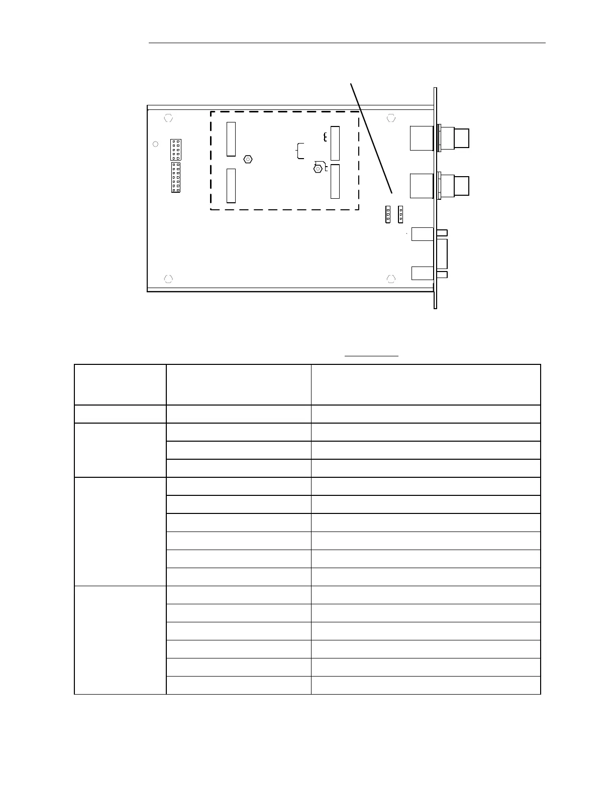
Figure 6-15. GARD 8000 3U System I/O module, board view showing jumper locations
Table 6-13. Jumpers required on GARD 8000 System I/O module
when optional GPS module is not installed
Jack Number (See
figures 6-13 or
6-15 as applicable)
Jumper Installed across these
two terminals (See figures 6-13
or 6-15 as applicable)
IRIG-B, AGC is in the circuit
For Unmodulated IRIG-B inputs
For Modulated IRIG-B inputs
50 Ohm IRIG-B termination
600 Ohm IRIG-B termination
IRIG-B shield is grounded
IRIG-B shield is isolated
6.6.1 IRIG-B WITH GPS