Power Line Carrier
GARD 8000 SYS RFL Electronics
April 23, 2015 10-29 973.334.3100
The function of the attenuator board is to provide 40dB of attenuation during loopback testing. Toggle
switch SW1 is used to select either Normal or Loopback operation. Test points TP1 and TP2 allow the
user to monitor the output of the attenuator.
10.8.9 MOTHER BOARD
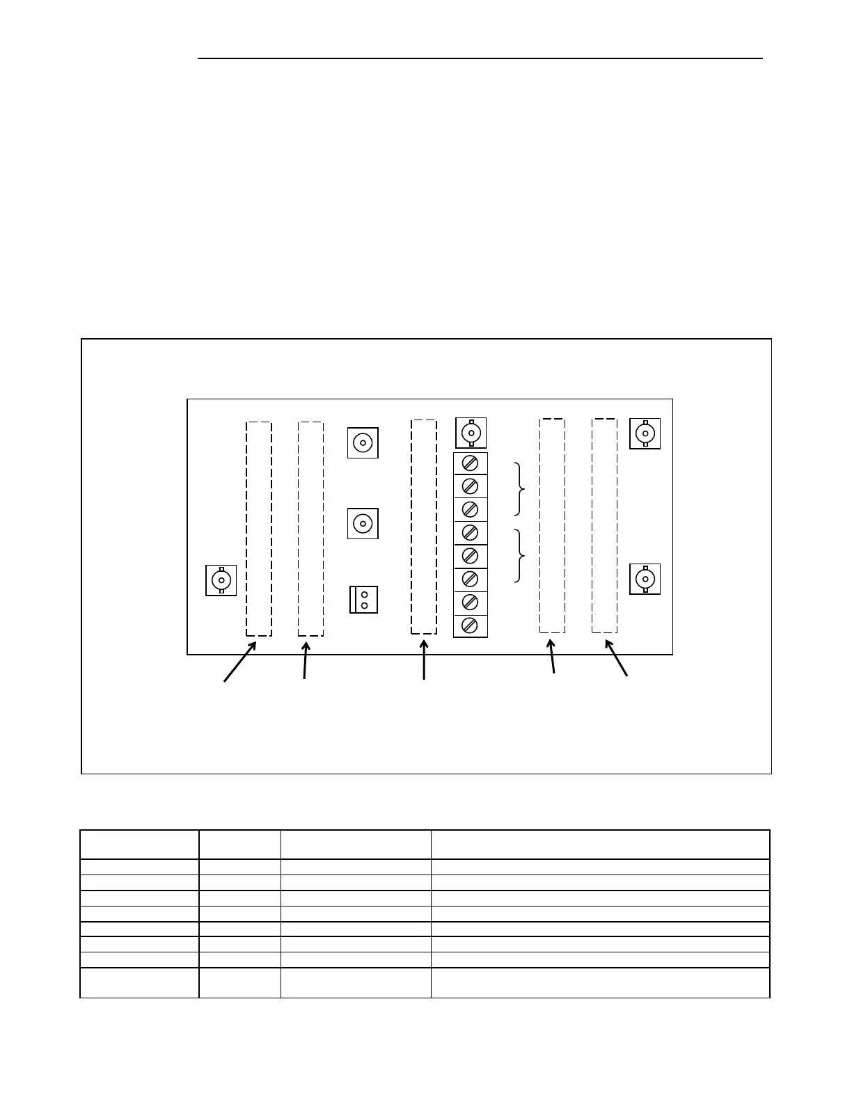
The RFL 9508 RF Motherboard is a 4.5 x 8 inch assembly, which is mounted on the rear right side of
the 9508 chassis as viewed from the front. It provides interconnections for the five RF modules that
plug into it from the front of the chassis, which are the Tx Filter, Balance Board, Line Board,
Attenuator Board, Rx Filter. The illustration below shows the rear view of the motherboard.
Connectors J6 and J7 are TNC connectors which provide connections to the line coupling equipment.
J4, J5, J8 and J9 are BNC connectors, J10 is a two pin plug-in connector, and TB1 is an eight position
terminal block.
Figure 10-21. RFL 9508 RF Mother Board, Rear View
Table 10-11. Motherboard Rear Panel Connector Assignments
Input signal from external amp
Output signal to external amp
4W Input from line coupling equipment
4W Output to line coupling equipment or 2W Input/Output
INT AMP FAIL
EXT AMP FAIL
8-position terminal block
Power Amplifier Fail, Relay Contacts
(See the following table for terminal assignments)
ATTENUATOR RX LINE BALANCE TX
BOARD FILTER BOARD BOARD FILTER
NOTE: Dotted lines indicate boards that plug into the motherboard from the front of the RFL 9508 chassis.
NO
NC
C
NO
NC
CHASSIS GND
EARTH GND
AMP
FAIL
EXT
AMP