Installation and Commissioning
GARD 8000 SYS RFL Electronics
November 28, 2017 4-51 973.334.3100
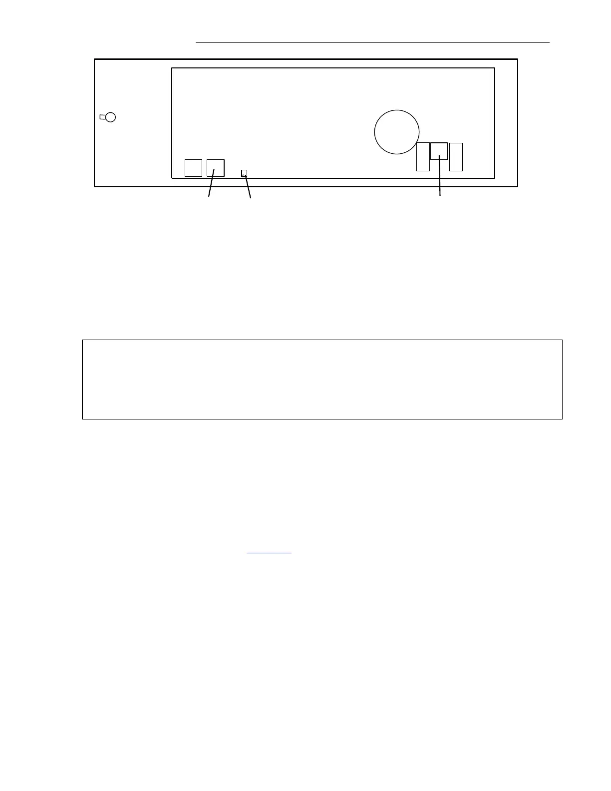
Figure 4-18. 50W Power Amplifier Circuit Board
3. Remove connector J5 (J4 located next to J5 is the same point electrically it does not matter
which connector is used. This connector MUST be removed before proceeding with the
connection of a dummy load at J2.
4. Remove connector J2, and install a 50 ohm dummy load; reinstall J5.
7. Adjust R83 for 15.8Vrms (+37dBm) while transmitting 5 watts using a frequency selective volt
meter. (FSVM) 50Vrms when transmitting 50 watts.
WARNING!
For Amplifiers built before October 2010 R83 will tune clockwise to lower gain and counter
clockwise to increase gain. For Amplifiers built October 2010 and later R83 tunes clockwise to
increase gain and counter clockwise to decrease gain. Monitor FSVM reading carefully while
adjusting R83.
8. For 100 watt systems repeat steps 5, 6 and 7 for the other 50 watt amp.
9. Again remove connector J5, then remove the dummy load and reinstall the connector at J2.
10. Reinstall the connector at J5.
11. The TX Filter was configured at the factory. If the transmit frequency was changed use the
9508 filter calculation macro provided with this equipment to set jumpers. Tune in accordance
with the steps shown in section 10.8.13.2 of this Instruction Manual.
12. Remove connector J5 from the Power Amplifier Circuit Board.
13. Disconnect the line coupling from the 2W I/O connector on the rear of the 9508 RF chassis and
connect a 50 ohm dummy load.
14. Reinstall the connector at J5.